What are CNC Turning and Milling Parts? An Essential Guide to Precision Components
- Share
- Issue Time
- Jun 9,2026
Summary
Explore CNC turning & milling parts: definitions, Swiss-type lathes, multi-axis milling, G-code, & applications in aerospace & medical industries.
As a professional, I've observed how Computer Numerical Control (CNC) machining has fundamentally transformed manufacturing, enabling the creation of exceptionally precise components. This technology represents the pinnacle of precision and efficiency in modern subtractive manufacturing.
In this comprehensive guide, we'll delve into CNC turning and milling parts – two foundational processes that produce the intricate and accurate components powering various industries today. We will explore the core components, operational capabilities, and strategic impact of these technologies on the modern production landscape.
Understanding CNC Turning Parts: Precision for Cylindrical Components
CNC turning is a manufacturing process where a block of material, the workpiece, is rotated while a single-point cutting tool is moved parallel to the axis of rotation. This process is ideal for creating cylindrical parts with various external and internal features. The CNC lathe, the machine tool used for turning, is a sophisticated piece of equipment composed of several critical components working in unison to achieve high precision.
Key Components and How They Function
A CNC lathe is an assembly of distinct parts, each with a specific function that contributes to the machine's overall accuracy and capability. Understanding these components is the first step to appreciating the elegance of the turning process. From the powerhouse of the headstock to the foundational support of the bed, every element is engineered for stability and precision.
Headstock, Chucks, Collets, Tailstock, and Lathe Bed Explained
To master CNC turning, one must first understand the anatomy of the lathe. These components are the building blocks of precision.
Headstock: The headstock is the powerhouse of the CNC lathe, located at the left end of the machine. It contains the main spindle, the critical rotating component driven by a powerful motor. The headstock's primary role is to hold the workpiece and rotate it at controlled speeds. Its robust construction is essential for minimizing vibrations and ensuring the rotational stability required for high-precision machining. The specifications of the headstock, such as its motor power and spindle bore diameter, directly define the lathe's capacity, including the maximum size of the material it can handle.
Chucks and Collets: These are the work-holding devices mounted on the spindle that grip the workpiece. The choice between a chuck and a collet depends on the job's specific requirements.
- Chucks: A chuck uses adjustable jaws to clamp onto a workpiece. Three-jaw chucks are common for gripping round or hexagonal stock quickly and are self-centering, while four-jaw chucks allow for independent jaw movement to hold irregularly shaped parts. Chucks are versatile and can accommodate a wide range of workpiece diameters, making them suitable for jobs with varied part sizes.
- Collets: A collet is a sleeve-like device that forms a collar around the material, gripping it tightly as it's drawn into a tapered bore. Collets provide 360-degree contact, distributing gripping force evenly, which is ideal for delicate, thin-walled parts and for maintaining concentricity. They are known for providing excellent precision and repeatability, especially in high-speed operations.
| Feature | Chuck (3-Jaw) | Collet |
|---|---|---|
| Gripping Method | Adjustable jaws clamp the workpiece. | A sleeve tightens around the workpiece. |
| Workpiece Shape | Best for cylindrical and hexagonal parts, but 4-jaw can hold irregular shapes. | Primarily for cylindrical, hex, or square stock of a specific size. |
| Precision | Good, but can be less concentric than a collet. | Excellent concentricity and high repeatability. |
| Gripping Force | High, but concentrated on jaw contact points. | Evenly distributed 360-degree force, reducing part distortion. |
| Best Use Case | Versatile for various part diameters and larger workpieces. | High-speed production, small-diameter parts, and delicate components. |
| Changeover Time | Slower, may require jaw adjustments or changes. | Very fast, allowing for quick part changeovers. |
Tailstock: Positioned on the bed opposite the headstock, the tailstock provides critical support for the end of a long workpiece. This support prevents the part from deflecting under the pressure of the cutting tool or "whipping" at high rotational speeds, which is essential for maintaining accuracy over the part's entire length. The tailstock can be fitted with a rotating "live center" to support the workpiece or with tools like drills and reamers for performing secondary operations on the part's centerline. For shorter, sturdier parts held securely in the chuck, the tailstock may not be necessary.
Lathe Bed: The lathe bed is the backbone of the entire machine. It is a heavy, rigid base, typically made from high-quality cast iron, which is known for its rigidity and vibration-damping properties. The bed supports and aligns all other major components, including the headstock, tailstock, and the carriage that carries the cutting tool. It features precision-ground rails, known as "ways," that guide the tailstock and carriage, ensuring their movement is perfectly parallel to the spindle's axis. The stability and precision of the bed are fundamental to the lathe's ability to produce accurate and consistent parts. Some modern lathes feature a "slant bed" design, which uses gravity to improve the removal of chips and can enhance rigidity.

Operations and Diverse Capabilities for Turning Parts
The true power of CNC turning lies in its automated, high-precision operations. These are controlled by a specific programming language and executed through complex, coordinated movements. The evolution of this technology has led to highly specialized machines, like Swiss-type lathes, that offer unique capabilities for producing intricate parts.
G-code Control, Multi-Axis Movement, and Swiss-Type Precision Turning
G-code Control: At the heart of every CNC machine's operation is G-code, the programming language used to give instructions for movement and function. G-code, which stands for "Geometric Code," tells the machine's controller exactly where to move, how fast to move, and which path to follow. A program consists of lines of code, or "blocks," where each block contains commands that the machine executes in sequence. For example:
- G-commands primarily control the geometry of the toolpath, such as rapid positioning (G00), linear cutting movements (G01), and circular or arc movements (G02/G03).
- M-codes (Miscellaneous codes) control machine functions like starting or stopping the spindle, turning coolant on or off, and executing a tool change.
- Other addresses like S define the spindle speed, F sets the feed rate, and T selects the tool. This code, often generated by Computer-Aided Manufacturing (CAM) software, allows for unimaginably complex and precise operations to be performed with perfect repeatability.
Multi-Axis Movement: While basic lathes operate on two axes (X for diameter and Z for length), modern CNC turning centers have evolved to include additional axes of motion. This greatly expands their capabilities beyond simple cylindrical parts.
- 2-Axis Turning: The foundation of CNC turning, involving X-axis (in/out) and Z-axis (left/right) movements to create profiles on a spinning part.
- 3-Axis Turning: Adds a C-axis (rotational control of the spindle) and live tooling (powered rotating tools in the turret). This allows the machine to stop the main spindle at a precise angle and perform secondary operations like drilling cross-holes, milling flats, or cutting keyways without moving the part to a different machine.
- 4-Axis Turning: Typically adds a Y-axis, which allows the live tools to move up and down, perpendicular to the X-axis. This enables the creation of more complex off-center features.
- 5-Axis Turning: Often incorporates a B-axis (a tilting head for the live tools) on top of the other axes. A 5-axis turning center can perform highly complex milling operations on a part in a single setup, rivaling the capabilities of a dedicated milling machine.
Swiss-Type Precision Turning: Swiss-type turning, also known as Swiss machining, is a specialized CNC turning process designed for producing small, long, and intricate parts with exceptionally high precision. Originally developed for the Swiss watchmaking industry, this method differs fundamentally from conventional turning.
In a conventional lathe, the workpiece is held in a chuck and rotates, while the tool moves to cut it. This can cause long, slender parts to deflect or vibrate. A Swiss-type machine solves this by using a sliding headstock and a guide bushing. The bar stock is fed through the guide bushing, and the cutting tools operate on the material right at the point where it exits the bushing. This provides rigid support to the workpiece at the point of cutting, virtually eliminating deflection and allowing for incredibly tight tolerances, even on very long and thin parts.
Key advantages of Swiss-type turning include:
- Exceptional Precision: Capable of holding tolerances as tight as ±0.0001 inches (0.0025 mm).
- Ideal for Complex Parts: Multi-axis Swiss machines can perform turning, milling, drilling, and other operations simultaneously, producing finished, complex parts in a single cycle.
- High Efficiency for Volume Production: While setup can be complex, the fast cycle times and ability to run unattended make Swiss machining highly cost-effective for large production runs.
- Superior Surface Finish: The stability provided by the guide bushing minimizes chatter and results in excellent surface finishes.
This makes Swiss turning the preferred method for manufacturing critical components in industries like medical (e.g., bone screws, dental implants), aerospace (e.g., precision fasteners, sensor components), and electronics (e.g., connectors, pins).

Exploring CNC Milling Parts: Crafting Complex Geometries with Accuracy
While CNC turning excels at creating cylindrical parts, CNC milling is the go-to process for producing complex, non-cylindrical shapes. In milling, the workpiece is held stationary while a rotating multi-point cutting tool moves around it to remove material. This method offers incredible design freedom, allowing for the creation of everything from simple geometric features like slots and pockets to highly complex 3D surfaces.
Mechanics and Control Systems of CNC Milling
The precision of CNC milling comes from its rigid mechanics and sophisticated digital control systems. The ability to move the cutting tool or workpiece along multiple axes, guided by a program translated from a 3D model, is what enables the creation of such intricate components.
Multi-Axis Movement (X, Y, Z, and Rotational) and CAM Software Integration
Multi-Axis Movement: The versatility of a CNC milling machine is largely defined by the number of axes it can control. These axes dictate the directions in which the cutting tool and workpiece can move relative to each other.
- 3-Axis Milling: This is the most common type of CNC milling. The machine operates along three linear axes:
- X-axis: Left-to-right movement.
- Y-axis: Front-to-back movement.
- Z-axis: Up-and-down movement. In a 3-axis machine, the spindle moves along these three axes to cut a stationary workpiece. It is perfect for producing parts with features that can be accessed purely from the top, such as drilled holes, pockets, and profiled edges.
- 4-Axis Milling: This configuration adds a rotational axis, known as the A-axis (which rotates around the X-axis). A 4-axis machine can rotate the workpiece, allowing it to be machined on multiple sides in a single setup. This is useful for creating features on the side of a part or for continuous cutting around a cylindrical component.
- 5-Axis Milling: This is the pinnacle of milling technology, adding two rotational axes to the three linear ones. These rotational axes can be configured in different ways, but they are typically:
- A-axis: Rotation around the X-axis.
- B-axis: Rotation around the Y-axis.
- C-axis: Rotation around the Z-axis. A 5-axis machine will use two of these three rotational axes, such as B and C. This allows the cutting tool to approach the workpiece from a virtually infinite number of angles, enabling the production of extremely complex shapes, deep cavities, and contoured surfaces in a single clamping. This capability is critical for industries like aerospace, where parts often have complex, organic geometries.
| Axis Configuration | Linear Axes | Rotational Axes | Capability | Typical Applications |
|---|---|---|---|---|
| 3-Axis | X, Y, Z | None | Machining on a single face of the workpiece. | Flat parts, pockets, drilled holes, simple profiles. |
| 4-Axis | X, Y, Z | A (or B) | Machining on multiple sides of the workpiece through rotation. | Engraving on cylinders, side holes, cam lobes. |
| 5-Axis | X, Y, Z | A and B, A and C, or B and C | Simultaneous machining on five sides of the workpiece from any angle. | Impellers, turbine blades, complex molds, medical implants. |
CAM Software Integration: The crucial link between a digital design and the physical CNC machine is Computer-Aided Manufacturing (CAM) software. While a design is created using Computer-Aided Design (CAD) software, the machine itself cannot understand a 3D model directly. CAM software acts as the translator.
The CAD-to-CAM workflow is a foundational process in modern manufacturing:
- CAD Model Import: A 3D model of the part is created in a CAD program and then imported into the CAM software.
- Toolpath Generation: The CAM programmer uses the software to define the machining strategy. This involves selecting the right cutting tools, setting cutting speeds and feed rates, and generating the specific paths the tool will follow to remove material. The software automates complex calculations to create efficient and collision-free toolpaths.
- Simulation: Before sending the program to the machine, the CAM software can run a detailed simulation. This visualizes the entire machining process, showing how material is removed and helping to identify potential errors, tool collisions, or inefficient movements. This verification step is crucial for preventing costly mistakes and machine damage.
- Post-Processing: Once the toolpaths are verified, the CAM software uses a "post-processor" to convert the generic toolpath data into a specific G-code program tailored for the exact make and model of the CNC machine being used. This G-code file contains all the instructions the machine controller needs to execute the job precisely.
This integration of CAD and CAM allows for the automated production of extremely complex parts with high precision and repeatability, a feat that would be impossible with manual programming. It significantly speeds up production, reduces the chance of human error, and optimizes material usage.

Applications and Material Versatility for Milled Components
The combination of multi-axis capability and a vast range of compatible materials makes CNC milling an exceptionally versatile manufacturing process. Its applications span nearly every industry, particularly those that demand complex parts with high strength and tight tolerances.
Producing Complex Parts for Aerospace, Medical, and Other Industries
The precision and design freedom of CNC milling have made it an indispensable technology in high-stakes sectors where failure is not an option.
Aerospace Industry: In aerospace, every component is critical. Parts must be incredibly strong and durable yet as lightweight as possible to maximize fuel efficiency and performance. CNC milling is essential for producing these mission-critical components with unparalleled precision.
- Engine Components: 5-axis CNC machines are used to create parts with complex aerodynamic contours, such as turbine blades, impellers, and blisks (bladed disks). The ability to machine these from a single block of high-temperature superalloy enhances their strength and reliability.
- Structural Components: Aircraft frames, wing spars, ribs, and bulkheads are milled from large billets of high-strength aluminum alloys. CNC milling allows for the creation of thin-walled structures and complex pockets that reduce weight without compromising structural integrity.
- Avionics and Interior Parts: The technology is also used to create housings for sensitive electronics, control panels, and custom interior modules that must meet strict dimensional and weight requirements.
Medical Industry: Precision, biocompatibility, and customization are paramount in medical device manufacturing. CNC milling is heavily relied upon to produce everything from standard surgical tools to patient-specific implants.
- Orthopedic Implants: CNC machines are used to manufacture custom and standard orthopedic implants, such as hip and knee replacements. Materials like titanium and medical-grade polymers are milled into complex shapes that are designed to fit a patient's anatomy perfectly.
- Surgical Instruments: The creation of high-quality surgical instruments like scalpels, forceps, clamps, and retractors requires the extreme precision of CNC milling to ensure sharpness, proper alignment, and ergonomic features.
- Dental Prosthetics: Dental labs use CNC milling extensively to create crowns, bridges, and abutments from materials like zirconia and ceramics, ensuring a flawless fit and natural appearance for the patient.
Other Industries: The applications of CNC milling extend far beyond aerospace and medical:
- Automotive: Manufacturing of engine blocks, pistons, transmission components, and molds for plastic parts.
- Electronics: Creating custom enclosures, heat sinks, and connectors with high precision.
- Energy: Production of turbine components for power generation and complex parts for oil and gas exploration.
- Prototyping: Rapidly creating functional prototypes for design validation across all product development sectors.
Material Versatility: One of the greatest strengths of CNC milling is its compatibility with a huge assortment of materials. The choice of material is critical and depends on factors like the required strength, weight, corrosion resistance, heat tolerance, and cost of the final part.
| Material Category | Common Examples | Key Properties & Applications |
|---|---|---|
| Metals | Aluminum (e.g., 6061, 7075) | Excellent strength-to-weight ratio, good machinability. Used for aerospace frames, automotive parts, consumer electronics. |
| Stainless Steel (e.g., 304, 316) | High strength, excellent corrosion resistance, sterilizable. Ideal for medical instruments, food processing equipment, marine hardware. | |
| Titanium | Very high strength-to-weight ratio, extreme corrosion resistance, biocompatible. Common in aerospace components and medical implants. | |
| Steel (e.g., Carbon, Alloy) | High strength, durability, and wear resistance. Used for gears, shafts, and structural components. | |
| Brass | Low friction, good electrical conductivity, corrosion resistant. Used for electrical connectors, fittings, and decorative parts. | |
| Plastics | ABS | Good impact resistance and toughness. Used for enclosures, prototypes, and consumer products. |
| Nylon | Excellent wear resistance, high strength. Used for gears, bearings, and structural components. | |
| PEEK | High-performance thermoplastic with excellent mechanical strength, chemical resistance, and temperature stability. Used in demanding aerospace, medical, and industrial applications. | |
| Acrylic (PMMA) | Optically clear, rigid. A lightweight, shatter-resistant alternative to glass, used for light pipes and transparent covers. | |
| Composites & Others | Carbon Fiber | Extremely high stiffness and strength-to-weight ratio. Used in high-performance aerospace and automotive parts. |
| Wood | Used for furniture, decorative items, and architectural models. |
This material versatility allows engineers and designers to select the perfect substance to meet the specific functional requirements of their component, which is then crafted into its final form with the exacting precision of CNC milling.
The Strategic Impact of CNC Turning and Milling Parts in Manufacturing
The integration of CNC turning and milling into manufacturing has done more than just automate production; it has strategically redefined the standards for quality, speed, and complexity. These technologies form the bedrock of modern industry, enabling advancements that were once considered impossible. Their impact is most profoundly felt in the core manufacturing tenets of precision, efficiency, and cost-effectiveness.
Unwavering Precision and Repeatability in Production
Perhaps the most significant advantage of CNC machining is its ability to produce parts with a level of precision and consistency that manual processes simply cannot match. This capability has become the new benchmark for quality across all sectors.
Achieving Micro-Level Tolerances and Enhanced Quality Assurance
Micro-Level Tolerances: Tolerance refers to the permissible limit of variation in a physical dimension of a part. In manufacturing, achieving tight tolerances is critical, especially for components that must fit together perfectly in an assembly. CNC machines excel at this, capable of holding standard tolerances around ±0.005 inches (0.127 mm), which is thinner than a human hair. For high-precision applications in fields like aerospace or medical devices, these tolerances can be pushed even further, reaching a level of accuracy measured in micrometers (microns). This micro-level precision is achieved through a combination of factors:
- Rigid Machine Construction: CNC machines are built with heavy, vibration-damping frames made of materials like cast iron or granite, which provide a stable foundation for the cutting process.
- Precision Components: The use of high-precision ball screws and linear guideways allows for smooth, controlled motion with minimal play or error.
- Closed-Loop Feedback Systems: Servo motors with encoders constantly monitor the exact position of the machine's axes and send feedback to the controller, which makes real-time adjustments to correct any deviation, ensuring the tool is always exactly where it's supposed to be.
Repeatability and Consistency: While accuracy refers to how close a measurement is to its target value, repeatability measures the ability to produce the same result over and over again. This is where CNC machining truly shines. A CNC program, once written and verified, can be run thousands of times to produce parts that are virtually identical. This consistency is fundamental to mass production and quality control, as it ensures that every part coming off the line will function as intended. Repeatability is key to reducing scrap rates and inspection time.
Enhanced Quality Assurance: Quality in CNC machining is not just inspected at the end; it is built into the entire process.
- Design and Simulation: The process begins with meticulous planning in CAD and CAM software, where potential issues can be identified and corrected virtually before any material is cut.
- In-Process Monitoring: During machining, advanced CNC systems can use probes to measure the workpiece in real-time. This allows for automated adjustments to compensate for tool wear or slight material variations, ensuring every part remains within its specified tolerance.
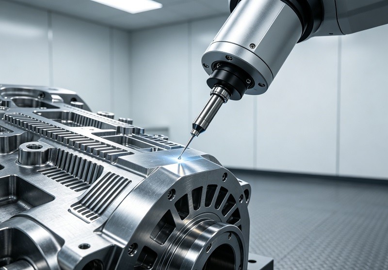
- Final Inspection: After a part is completed, it undergoes a final quality control check. This often involves using a Coordinate Measuring Machine (CMM), a device that uses a highly sensitive probe to measure the geometry of an object with incredible accuracy. The CMM compares the physical part's dimensions against the original CAD model to verify that it meets all specifications.
This multi-stage quality assurance framework, from digital design to final inspection, ensures that CNC machined parts meet the most stringent quality standards, building trust and reliability into the final product.
Driving Efficiency, Versatility, and Cost-Effectiveness
Beyond precision, CNC technology is a powerful engine for operational excellence. By automating complex processes, it allows manufacturers to accelerate production, utilize resources more effectively, and adapt to changing market demands with agility.
Accelerated Production Cycles, Optimal Resource Utilization, and Scalability
Accelerated Production Cycles: In today's fast-paced market, speed is a critical competitive advantage. CNC machining drastically reduces lead times compared to manual methods. The aautomated nature of CNC machines allows them to operate continuously, 24/7, with minimal human supervision. High-speed machining (HSM) techniques, which use very high spindle speeds and feed rates, can dramatically shorten the time it takes to produce a part. This acceleration is compounded in multi-axis machines, which can perform multiple operations in a single setup, eliminating the time-consuming process of moving a workpiece from one machine to another for different operations.
Optimal Resource Utilization: CNC machining drives cost-efficiency by making the most of every resource.
- Labor Efficiency: A single skilled operator can oversee multiple CNC machines at once, significantly reducing direct labor costs compared to manual machining where one operator is tied to one machine. This frees up skilled workers to focus on higher-value tasks like programming, setup, and quality assurance.
- Material Savings: CAM software is designed to create optimized toolpaths that remove material in the most efficient way possible, minimizing scrap. The high precision of the process means fewer parts are rejected for being out of tolerance, further reducing material waste and the associated costs.
Scalability: Scalability is the ability to easily ramp production up or down to meet demand, and it is a core strength of CNC manufacturing.
- From Prototype to Production: The same digital file (CAD model) and program (G-code) can be used to create a single prototype, a small batch of test parts, or a full-scale production run of thousands or even millions of components.
- Flexibility and Adaptability: This digital workflow makes it easy to adjust production volumes quickly. If demand for a product increases, more machines can be assigned to run the same program. If a design needs to be updated, the CAD file can be modified and a new G-code can be generated with minimal downtime.
This combination of speed, resource optimization, and seamless scalability makes CNC turning and milling an incredibly powerful and cost-effective solution for modern manufacturing, from initial concept to mass production.
Conclusion
In summary, CNC turning and milling parts are the cornerstones of modern manufacturing, delivering the essential precision, unwavering consistency, and incredible versatility required for today's most advanced components. From the foundational accuracy of turning cylindrical parts to the geometric freedom of milling complex shapes, these automated processes have fundamentally elevated what is possible in industrial production.
Looking forward, these technologies are set to evolve even further. The integration of artificial intelligence, machine learning, and in-process metrology will continue to push the boundaries of automation, quality, and efficiency. As new materials are developed and part complexity increases, CNC turning and milling will remain at the forefront, enabling innovation and creating the high-quality precision parts that will define the future of engineering across all existing and emerging industries.
We invite you to share this guide with colleagues and to leave your thoughts in the comments below. What future advancements in CNC machining are you most excited about?