The Engineer's Guide to Selecting Custom OEM CATV Connectors for Coaxial Cables.
- Share
- Issue Time
- May 28,2026
Summary
Learn key tips for choosing custom OEM CATV coaxial connectors, including impedance, frequency, shielding and durability for reliable signal transmission.
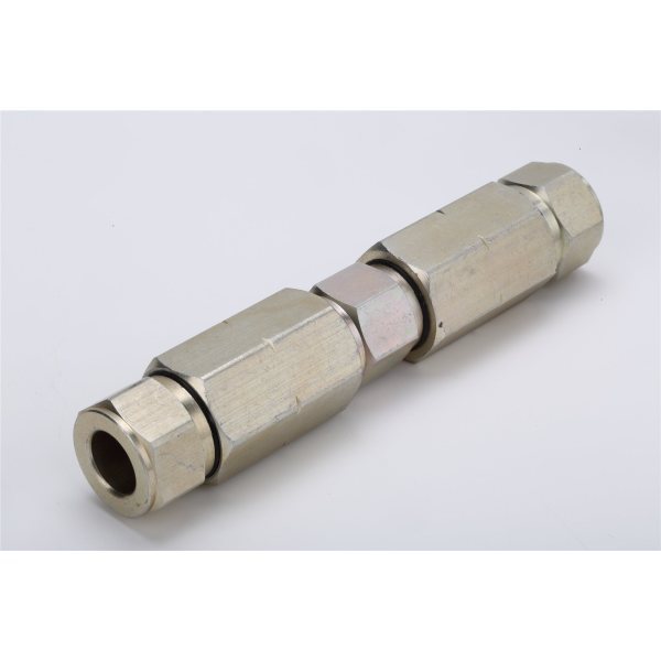
As engineers, we understand that a strong, clear signal is paramount for any CATV system. A reliable connection is the foundation of performance, and it all begins with the right components—specifically, the right coaxial cable connectors. While generic, off-the-shelf connectors might suffice for basic applications, they often fall short when faced with the specific demands of complex or high-performance projects. This is where Custom OEM CATV Connectors come into play, offering tailored solutions engineered for optimal performance and unwavering reliability.
This guide is designed for engineers who require precision and durability. We will delve into the critical aspects of selecting custom OEM CATV connectors, from material science and electrical specifications to the intricacies of the manufacturing process. Our goal is to equip you with the knowledge to ensure your systems deliver the best possible performance, every time.
Understanding Why Custom OEM CATV Connectors Are Essential for Peak Performance
The term "connector" can sometimes understate its importance. In a CATV system, the connector is not just a point of termination; it is a critical component that can either preserve or degrade signal integrity. Understanding the distinction between standard and custom OEM connectors is the first step toward building a truly robust and reliable network.
What Exactly Are CATV Connectors?
At their core, CATV (Community Antenna Television) connectors are specialized electrical components designed to terminate coaxial cables. They create a secure and continuous link between the cable and a device, such as a television, modem, or distribution amplifier.
The Basic Job of a Coaxial Cable Connector
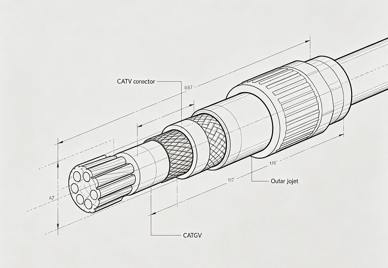
The primary function of a coaxial cable connector is to create a secure, reliable connection between a coaxial cable and a piece of equipment, ensuring the uninterrupted flow of high-frequency signals. A coaxial cable is composed of a central conductor that carries the signal, a dielectric insulator, a metallic shield, and an outer protective jacket. The connector's job is to seamlessly extend this structure. It ensures the center conductor of the cable makes direct contact with the corresponding point on the device, while also maintaining the continuity of the outer shield. This complete connection protects the signal from external electromagnetic interference (EMI) and minimizes signal loss.
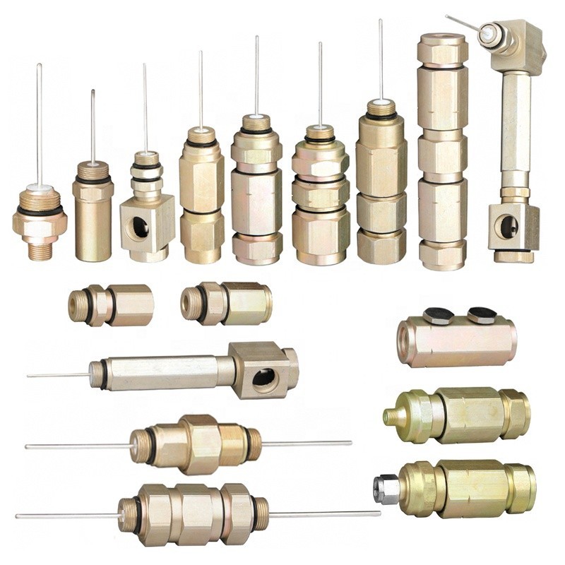
Why Quality Directly Impacts Your TV Signal
The quality of a CATV connector is not a trivial detail; it is a determining factor in the overall performance of the system. A low-quality connector can introduce a host of problems that degrade the signal and lead to a poor user experience. These issues include:
- Signal Loss (Attenuation): Every connection point introduces a small amount of signal loss, but poorly made connectors have significantly higher loss. This weakens the signal, leading to issues like a snowy picture on analog channels or tiling and freezing on digital channels. High-quality connectors are designed to minimize this loss, a factor known as insertion loss.
- Impedance Mismatch: Coaxial systems for CATV are built on a standard impedance of 75 Ohms. If a connector's impedance deviates from this standard, it creates a mismatch. This mismatch causes a portion of the signal to be reflected back towards the source, a phenomenon called return loss. These reflections can interfere with the primary signal, causing ghosting, poor picture clarity, and data errors in internet signals.
- Poor Shielding: A connector's shield is just as important as the cable's shield. A low-quality connector may have inadequate shielding, making the connection point a gateway for outside radio frequency interference (RFI) and electromagnetic interference (EMI). This interference manifests as noise in the signal, causing random pixels, lines on the screen, or intermittent drops in internet service.
- Physical Instability: Loosely fitting connectors or those made from soft, easily deformable materials can lead to intermittent connections. Even a microscopic gap can act as a filter, cutting out higher frequency signals which are crucial for high-definition channels and high-speed data. Furthermore, a loose connection is no longer weatherproof, allowing moisture to enter and corrode the internal contacts, leading to rapid signal degradation.
A high-quality connector mitigates these issues by providing a secure mechanical fit, precise impedance matching, and robust shielding, thereby preserving the integrity of the signal from source to destination.
Why 'Custom' and 'OEM' Make a Difference for Custom OEM CATV Connectors
While standard connectors are designed for a broad range of general applications, they may not be the optimal choice for every project. The terms 'Custom' and 'OEM' (Original Equipment Manufacturer) signify a higher level of specialization and quality control that is critical for demanding engineering applications.
Tailoring Solutions to Specific Project Needs
The term "custom" implies that a connector can be designed or modified to meet the exact needs of a specific application. Off-the-shelf parts are made for general-purpose use, which may force engineers to design around the component's limitations. Customization flips this dynamic, allowing the component to be built around the project's unique requirements. This can involve:
- Unique Physical Dimensions: Designing a connector to fit into a tight or unusually shaped enclosure where a standard connector would not.
- Specific Material Requirements: Selecting specific metals, platings, and dielectrics to withstand harsh environmental conditions like extreme temperatures, moisture, or corrosive elements.
- Enhanced Electrical Performance: Engineering the connector to meet stringent performance targets for characteristics like very low insertion loss or high shielding effectiveness in a noisy RF environment.
- Specialized Mating Mechanisms: Creating custom locking or coupling mechanisms for applications requiring high vibration resistance or quick-disconnect capabilities.
By tailoring a solution, engineers are not forced to compromise. Customization ensures that the connector is a perfect fit, both mechanically and electrically, leading to improved performance and reliability.
The Benefits of Original Equipment Manufacturing Consistency
Original Equipment Manufacturer (OEM) refers to a company that produces parts and equipment that may be marketed by another manufacturer. For engineers, sourcing OEM components offers several distinct advantages rooted in consistency and quality control.
- Guaranteed Quality and Reliability: OEM parts are manufactured to a precise set of specifications and standards. This ensures that every connector from a given batch will perform identically to the last. Unlike aftermarket parts, which can have wide variations in quality, OEM components offer predictable and reliable performance. This is crucial in large-scale deployments where consistency is key to system stability.
- Strict Quality Control: Reputable OEM manufacturers implement rigorous quality control processes at every stage of production. This includes incoming material inspection, in-process monitoring, and final testing of the finished product. Adherence to international standards like ISO 9001 provides a framework for these quality management systems, ensuring that every connector meets or exceeds its specified performance criteria.
- Long-Term Partnership and Support: Working with an OEM fosters a long-term relationship that goes beyond a simple transaction. This provides access to engineering support, detailed documentation, and a reliable supply chain. If a design needs to be revised or a new project requires a similar component, the foundation of knowledge and trust is already established. This mitigates risks associated with supply chain disruptions and ensures a consistent, uninterrupted production flow for future needs.
In short, choosing an OEM partner means investing in a component that is guaranteed to fit, perform reliably, and be available with consistent quality for the lifespan of the project and beyond.
Key Factors We Consider When Selecting Custom OEM CATV Connectors
Selecting the right custom OEM CATV connector is a multi-faceted process that requires a deep understanding of materials, electrical principles, and environmental stresses. As engineers, we must balance these factors to achieve a final product that is not only high-performing but also durable and cost-effective for the intended application.
Material Choices and Connector Durability
The materials used to construct a connector are fundamental to its longevity and performance. The choice of metals and protective platings directly influences its mechanical strength, conductivity, and resistance to environmental degradation.
What Metals Work Best and Why
The selection of the base metal for a connector's body and contacts is a trade-off between conductivity, mechanical strength, machinability, and cost. Several metals are commonly used in the manufacturing of high-quality CATV connectors:
- Brass: This alloy of copper and zinc is the most common material for connector bodies. It offers a good balance of conductivity, strength, and excellent machinability, which helps keep manufacturing costs down. While its conductivity is lower than pure copper, it is more than sufficient for most CATV applications, especially when properly plated.
- Beryllium Copper (BeCu): For critical components like the center contact pin or internal spring contacts, beryllium copper is a superior choice. It possesses high strength, excellent elasticity (springiness), and conductivity that is far better than brass. This elasticity ensures that the connector maintains a reliable mechanical and electrical connection even after multiple mating cycles. Its high cost usually reserves it for high-performance or high-reliability applications.
- Phosphor Bronze: Often used as an alternative to beryllium copper for spring contacts, phosphor bronze offers good mechanical strength and spring properties. While its conductivity is lower than BeCu, it provides a durable and reliable connection at a more moderate cost.
- Stainless Steel: For the connector body or coupling nut in applications requiring extreme durability and corrosion resistance, stainless steel is the preferred material. Its high hardness makes it resistant to physical damage and thread stripping. However, it is more difficult to machine and has lower conductivity than brass, so it is typically reserved for the outer structural components rather than the signal path itself.
Below is a table summarizing the key properties of these common connector metals:
| Material | Key Properties | Common Uses in CATV Connectors |
|---|---|---|
| Brass | Excellent machinability, good conductivity, cost-effective. | Connector bodies, coupling nuts, outer barrels. |
| Beryllium Copper | High strength, excellent elasticity, high conductivity. | Center contact pins, female spring contacts. |
| Phosphor Bronze | Good strength and spring properties, moderate cost. | Alternative for spring and socket contacts. |
| Stainless Steel | Superior durability, high corrosion resistance, high hardness. | Connector bodies and hardware for harsh environments. |
Protecting Against Corrosion and Wear
Even the best base metals require protection. Plating is a micro-thin metallic coating applied over the base metal to enhance its properties. The primary functions of plating are to improve corrosion resistance, increase wear resistance, and ensure low, stable electrical contact resistance.
- Nickel Plating: Often used as both a primary finish and a barrier underlayer for other precious metals. Nickel is hard, provides excellent wear resistance, and offers good corrosion protection in most environments. It is a cost-effective solution for connector bodies and coupling nuts where durability is a primary concern. However, its conductivity is lower than that of gold or silver.
- Gold Plating: Gold is a noble metal, meaning it does not oxidize or corrode under normal conditions. This makes it the ideal choice for contact surfaces, as it maintains a clean, low-resistance connection over time, even in humid or corrosive environments. It is especially critical for low-voltage digital signals where even a thin oxide layer could disrupt the signal. Due to its cost, it is often applied selectively only to the critical contact areas.
- Silver Plating: Silver offers the highest electrical conductivity of any metal, even better than gold. This makes it suitable for high-frequency applications where minimizing signal loss is critical. However, silver is prone to tarnishing (oxidizing) in the presence of sulfur compounds. While silver sulfide is more conductive than the oxides of other metals, it is still a consideration for long-term stability.
- Tri-Metal/Alloys (e.g., Tin-Zinc): Many modern connectors use advanced alloys, often called tri-metal or white bronze platings (typically a mix of copper, tin, and zinc). These alloys are engineered to provide a combination of excellent corrosion resistance (often surpassing nickel), good conductivity, and a non-magnetic finish, which is important for minimizing intermodulation distortion in multi-carrier signal environments.
For outdoor applications, additional weatherproofing measures, such as silicone grease and self-fusing silicone tape, are essential to protect the connection from moisture ingress, which is a primary cause of connector failure. A well-greased, properly wrapped connection will remain protected from corrosion for years.
Electrical Performance Specifications for Custom OEM CATV Connectors
Beyond the physical materials, a connector's performance is defined by a set of critical electrical specifications. For engineers, understanding these parameters is non-negotiable for designing a system that maintains high signal integrity.
Impedance Matching: Keeping Signals Clear
Impedance is the measure of opposition to an alternating current and is a fundamental property of any transmission line, including coaxial cables and connectors. For CATV and most video applications, the industry standard characteristic impedance is 75 Ohms. This specific value was chosen because research by Bell Labs in the early 20th century found it to be the sweet spot for minimizing signal attenuation (loss) in coaxial cables with common dielectric materials.
A seamless 75 Ohm path from the source to the load is critical for preventing signal degradation. Here’s why:
- Maximum Power Transfer: When the impedance of the source, connector, cable, and load are all matched (e.g., all are 75 Ohms), the maximum amount of signal power is transferred from one component to the next.
- Minimizing Signal Reflections: Any point in the signal path where the impedance changes—an "impedance mismatch"—will cause a portion of the signal energy to be reflected back toward the source. These reflections interfere with the forward-traveling signal, leading to a variety of issues:
- Ghosting or Echoes: In analog video, reflections can cause faint duplicate images to appear on the screen.
- Data Errors: For digital signals, including high-speed internet (DOCSIS) and digital TV, reflections increase the Bit Error Rate (BER), leading to packet loss, slow speeds, and picture "tiling" or freezing.
- Standing Waves: The interference between the forward and reflected waves creates standing waves on the cable, which result in points of high and low signal amplitude along its length. This can cause some channels to be strong while others are weak.
A custom OEM connector is precisely engineered to maintain a consistent 75 Ohm impedance throughout its structure. This is achieved through careful geometric design of the pin diameter, the inner dimension of the outer shield, and the precise properties of the dielectric insulator material separating them. Any deviation in these dimensions can alter the impedance and compromise signal integrity.
Shielding Effectiveness: Blocking Unwanted Interference
Shielding is what protects a signal from the noisy outside world. Electromagnetic interference (EMI) and radio frequency interference (RFI) are all around us, emanating from power lines, electric motors, radio transmitters, and even adjacent data cables. The shielding in a coaxial cable acts as a barrier, preventing this unwanted energy from corrupting the signal an an RF connector must provide a 360-degree continuation of that shield.
Shielding Effectiveness (SE) is a measure of how well a connector can block this interference, and it is usually expressed in decibels (dB). A higher SE value indicates better performance. A connector with poor shielding can be the weakest link in an otherwise well-shielded system, acting as an antenna that either picks up external noise or leaks signal out.
This can cause a variety of problems:
- Ingress Noise: External signals leaking into the cable. This is a major cause of picture pixelation, tiling, and slow or intermittent internet service. The noise floor of the system rises, reducing the signal-to-noise ratio (SNR) that is critical for reliable digital communication.
- Egress Noise: The CATV signal leaking out of the cable. This is a serious issue as it can interfere with licensed over-the-air communications, such as aviation or emergency services frequencies. Cable operators can face significant fines for egress issues.
A quality custom OEM connector ensures high shielding effectiveness through its mechanical design. This includes a tight, 360-degree connection between the connector body and the cable's braided shield, as well as a robust interface where two connectors mate. There should be no gaps or "pigtail" ground connections, as these can severely compromise the shield's integrity. Custom connectors can be specifically engineered to meet or exceed Cenelec Class A++ shielding standards, providing more than 95 dB of shielding effectiveness and ensuring a clean, interference-free signal path.
Understanding Return Loss and Insertion Loss
These two parameters, both measured in decibels (dB), are the most fundamental metrics for quantifying connector performance. They describe two different aspects of how a connector affects the signal passing through it.
Return Loss (RL): Return Loss measures the amount of signal that is reflected back towards the source due to impedance mismatches. It is a ratio of the incident power to the reflected power.
- What it means: A high Return Loss value is good. It indicates that the impedance match is excellent and very little signal is being reflected. A low Return Loss value is bad, signifying a significant impedance mismatch and a large amount of reflected power.
- Why it matters: As discussed, reflected signals interfere with the main signal, causing data errors and picture degradation.
- Engineering Goal: For high-performance CATV systems, a connector should have a high return loss, often specified as greater than 25 dB or even 30 dB across the entire frequency range (5 MHz to over 1 GHz). Infinite return loss would be a perfect, reflection-free connection.
Insertion Loss (IL): Insertion Loss, also known as attenuation, measures the amount of signal strength that is lost as the signal passes through the connector.
- What it means: A low Insertion Loss value is good. It indicates that the connector is very efficient and loses very little signal power. A high Insertion Loss value is bad, as it means the connector is significantly weakening the signal.
- Why it matters: Every component in a CATV distribution system (cables, splitters, connectors) adds to the total insertion loss. While some loss is unavoidable, minimizing it at every point is crucial. Excessive insertion loss can weaken the signal to the point where it is unusable by the time it reaches the subscriber's equipment.
- Engineering Goal: A well-designed connector should have a very low insertion loss, typically less than 0.1 dB at lower frequencies and not exceeding a few tenths of a decibel (e.g., < 0.5 dB) even at the highest frequencies of the CATV spectrum.
In summary, the ideal connector is "invisible" to the signal—it introduces minimal insertion loss (low IL value) and causes minimal reflections (high RL value). Custom OEM connectors are designed and tested to meet stringent specifications for both of these critical parameters.
| Parameter | What It Measures | Good Value | Bad Value | Impact of Bad Value |
|---|---|---|---|---|
| Return Loss (RL) | Signal reflected back to the source | High (e.g., >25 dB) | Low (e.g., <15 dB) | Signal distortion, data errors, ghosting |
| Insertion Loss (IL) | Signal lost passing through the connector | Low (e.g., <0.2 dB) | High (e.g., >0.5 dB) | Weak signal, poor SNR, channel loss |
Environmental Resilience of Custom OEM CATV Connectors
Beyond electrical performance, the ability of a connector to withstand its operating environment is crucial for ensuring long-term reliability. Environmental factors can quickly degrade a poorly designed connector, leading to system failure.
Resistance to Heat, Cold, and Moisture
Connectors are often the most exposed part of a system, and they must be able to function reliably despite wide temperature swings, humidity, and direct contact with moisture.
- Temperature Extremes: Materials expand and contract with temperature changes. In a connector, this can lead to serious problems. For instance, extreme cold can cause materials to contract, potentially creating micro-gaps at the mating interfaces and leading to signal loss or intermittent connections. This phenomenon, known in the field as "suck-out," occurs when the center conductor physically shrinks and pulls back from the contact point. Conversely, high heat can cause materials to expand, potentially damaging internal components or causing the dielectric material to soften, which alters the connector's impedance. Custom connectors use materials with compatible coefficients of thermal expansion to minimize these effects and are subjected to thermal shock testing (e.g., per EIA-364-32) to ensure they can withstand rapid temperature changes.
- Moisture and Humidity: Moisture is the enemy of any electrical connection. In high-humidity environments, moisture can be absorbed by the cable's dielectric or become trapped within the connector. This has two major effects: it changes the impedance of the connection, causing signal reflections, and it accelerates corrosion. When water infiltrates a connector, especially in the presence of salt air in coastal regions, it can quickly corrode the pins and internal surfaces, leading to a complete failure of the connection.
Choosing for Outdoor Versus Indoor Applications
The intended location of a connector—whether indoors in a climate-controlled headend or outdoors on a utility pole—is a primary factor in its design and selection.
Indoor Applications: For connectors used indoors, the primary concerns are often density, ease of use, and electrical performance. Environmental protection is less critical, so simpler, non-sealed connectors are typically sufficient. However, shielding is still paramount, especially in a headend or data center environment packed with potential sources of EMI.
Outdoor Applications: Outdoor connectors face a much harsher reality. They must be designed to be completely weatherproof. This involves several key features:
- IP Rating (Ingress Protection): Connectors intended for outdoor use should have a high IP rating. The IP code consists of two digits: the first for protection against solids (like dust) and the second for liquids. An IP67 rating means the connector is completely dust-tight and can withstand temporary immersion in water. For even more demanding environments with high-pressure water jets or prolonged submersion, an IP68 rating is required.
- Sealing Mechanisms: High-quality outdoor connectors incorporate internal and external sealing mechanisms, typically using O-rings made from durable materials like silicone or EPDM rubber. These seals create a barrier at the cable entry point and at the mating interface, preventing water and dust from penetrating the connector.
- UV Resistance: Materials used for the outer body and any exposed non-metallic parts must be UV-stabilized to prevent them from becoming brittle and cracking after long-term exposure to sunlight.
- Corrosion-Resistant Materials and Plating: As discussed previously, outdoor connectors must be constructed from and plated with materials that can resist atmospheric corrosion. Stainless steel bodies and nickel or tri-metal alloy plating are common choices for ensuring long-term durability in wet or salt-spray environments.
By carefully selecting a connector with the appropriate environmental protections, engineers can ensure the long-term reliability and performance of the CATV system, minimizing costly service calls and downtime.
The Design and Manufacturing Journey of Custom OEM CATV Connectors
Creating a custom connector that meets precise engineering demands is a meticulous process that spans from initial concept to final production. This journey combines collaborative design, precision manufacturing techniques, and rigorous quality assurance to produce a component that delivers on its promises of performance and reliability.
From Blueprint to Production: Our Design Process
The journey of a custom connector begins long before any metal is cut. It starts with a comprehensive design process focused on translating a client's unique requirements into a manufacturable and reliable product.
How We Customize to Your Exact Specifications
The customization process is a collaborative effort between the client's engineering team and the manufacturer's design experts. It follows a structured approach to ensure all requirements are met:
Requirement Definition: The process starts with a deep dive into the project's needs. This involves detailed discussions to understand the essential electrical, mechanical, and environmental specifications. Key questions include:
- What are the target values for impedance, return loss, and insertion loss?
- What are the required shielding effectiveness levels?
- What are the dimensional constraints (size, shape, mounting)?
- What environmental conditions will the connector face (temperature range, humidity, UV exposure, chemical contact)?
- What is the required mating cycle life?
Conceptual Design and Material Selection: Based on the defined requirements, engineers develop initial concepts. This includes selecting the appropriate base metals and plating for each component part to balance performance, durability, and cost. Advanced CAD software is used to create 2D and 3D models of the proposed design.
Simulation and Analysis: Before creating physical parts, the design is subjected to simulation and analysis. Finite Element Analysis (FEA) can predict how the connector will behave under mechanical stress, while electromagnetic simulation tools model its electrical performance, predicting impedance, return loss, and shielding effectiveness. This digital analysis helps identify and correct potential design flaws early, saving time and cost.
Client Review and Approval: The proposed design, along with the analysis results, is presented to the client. This collaborative review ensures the design fully aligns with their expectations. Any necessary adjustments are made before moving to the prototyping stage. This iterative loop of feedback and refinement is crucial for achieving a truly custom solution.
The Importance of Prototyping and Rigorous Testing
A design that exists only on paper or in a CAD file is unproven. Prototyping and testing are where the theoretical design meets the physical world. This phase is indispensable for validating performance and identifying potential issues before committing to mass production.
The Role of Prototyping: A prototype is an early, functional model of the connector. It allows engineers to physically evaluate the design for form, fit, and function. While 3D printing can be used for initial form/fit checks, true functional prototypes are typically machined to the exact specifications of the final design. This tangible model is crucial for:
- Verifying Mechanical Fit: Ensuring the connector mates properly with its counterpart and fits within the designated enclosure.
- Early Performance Testing: Allowing for initial electrical and mechanical tests to confirm the design is on the right track.
- Identifying Manufacturing Challenges: The process of creating a prototype can reveal unforeseen difficulties in manufacturing the part, allowing for design adjustments to improve manufacturability (Design for Manufacturing, DFM).
Rigorous Testing and Validation: Once prototypes are made, they undergo a battery of tests to validate every aspect of their performance against the initial requirements. This is not a simple pass/fail check; it is a comprehensive evaluation to ensure reliability. Common tests include:
- Electrical Testing: Using a Vector Network Analyzer (VNA) to precisely measure return loss, insertion loss, and impedance across the full frequency spectrum.
- Mechanical Testing: Measuring mating/unmating forces, contact retention force, and durability over a specified number of cycles.
- Environmental Testing: Exposing the connector to harsh conditions to simulate its service life. This includes thermal shock (rapid temperature changes), humidity exposure, salt spray tests for corrosion resistance (per EIA-364-26), and vibration testing.
Discovering a design flaw during prototyping might cost a few thousand dollars and a few weeks of time. Discovering that same flaw after thousands of units have been produced can cost hundreds of thousands of dollars, delay project timelines by months, and damage a company's reputation. Prototyping and testing are the essential quality gates that prevent costly errors and guarantee a reliable final product.
Precision Manufacturing: The Role of CNC Turning in Custom OEM CATV Connectors
The performance of a high-frequency connector is directly tied to the precision of its physical dimensions. To achieve the tight tolerances required, manufacturers rely on advanced techniques like Computer Numerical Control (CNC) turning.
Understanding CNC Turning Technology
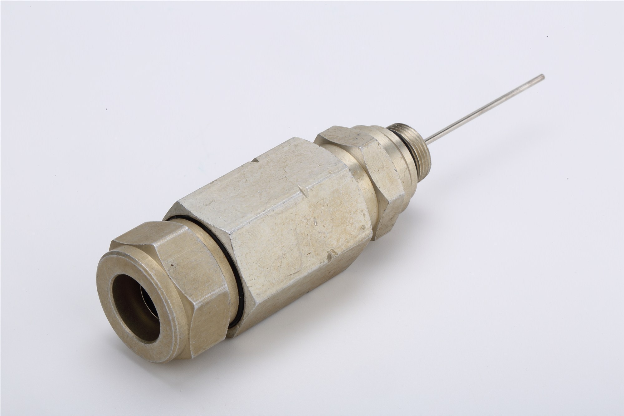
CNC turning is a subtractive manufacturing process where a bar of material (the workpiece) is rotated at high speed while a cutting tool is moved along its surface to remove material and shape the part. The entire process is controlled by a computer, which executes a pre-programmed set of instructions (G-code) derived from the CAD model.
Here's how it works:
- A rod of the chosen metal (e.g., brass, stainless steel) is clamped into the chuck of a CNC lathe, which begins to rotate it at thousands of RPM.
- A turret, holding multiple cutting tools, is programmed to move into position.
- The cutting tools, guided by the CNC program, move along the X (radial) and Z (lengthwise) axes to precisely carve away material from the spinning rod.
- Different tools are used for different operations, such as roughing passes to remove bulk material, finishing passes for a smooth surface, creating threads, and cutting grooves.
- Modern multi-axis CNC turning centers can even perform secondary operations like milling or drilling in the same setup, allowing for the creation of very complex parts in a single cycle.
This automated process ensures that every part produced is identical to the last, with extremely high precision and consistency.
Why Precision is Key for Reliable Connections
In the world of high-frequency signals, physics is unforgiving. Even microscopic variations in a connector's dimensions can have a macroscopic impact on its electrical performance. This is why precision manufacturing is not just a goal, but a necessity.
- Impact on Impedance: As previously mentioned, a connector's characteristic impedance is a direct function of its physical geometry: the ratio of the outer conductor's inner diameter to the center conductor's outer diameter, and the dielectric constant of the insulator between them. CNC turning allows these critical dimensions to be controlled with tolerances measured in micrometers (microns).
- A slight deviation—even a few thousandths of an inch—can cause the impedance to shift away from the target 75 Ohms. This shift creates the impedance mismatches that lead to signal reflections (poor return loss) and degradation of signal quality.
- Ensuring Consistency: CNC machining's primary advantage is its repeatability. Once a program is perfected, a CNC machine can produce thousands of identical parts. This ensures that every connector in a production run will have the same electrical characteristics. For large-scale CATV system deployments, this consistency is critical for predictable and reliable network performance. Manual or less precise manufacturing methods simply cannot deliver this level of uniformity.
- Mating Interface Integrity: The precision of the mating surfaces—where two connectors join—is vital for a reliable, low-loss connection. CNC turning ensures that threads are perfectly cut for smooth coupling and that the contact surfaces align perfectly. This guarantees both a solid mechanical connection and a continuous, low-resistance electrical path, which is essential for minimizing insertion loss.
In essence, the reliability advertised on a spec sheet is born from the precision on the manufacturing floor. Without the micron-level accuracy afforded by CNC turning, achieving the demanding performance required for modern, high-bandwidth CATV and data systems would be impossible.
Quality Assurance and Final Testing for Our Custom OEM CATV Connectors
The manufacturing journey doesn't end when the part comes off the CNC machine. A comprehensive quality assurance (QA) program ensures that every connector that leaves the factory meets the high standards set during the design phase. This final gatekeeping step is crucial for delivering a truly reliable product.
Ensuring Every Connector Meets High Standards
A multi-layered QA process is essential for guaranteeing that every single connector meets its specified performance and reliability targets. This process involves checks at every stage, from raw material to finished product.
- In-Process Inspection: Quality checks are not just reserved for the end of the line. Throughout the manufacturing process, automated optical inspection (AOI) systems and manual checks are used to monitor critical dimensions and surface finishes. This allows for the early detection and correction of any deviations from the specification, improving yield and ensuring consistency.
- Batch Testing vs. 100% Inspection: The choice between testing a statistical sample from a production batch (batch testing) or inspecting every single unit (100% inspection) depends on the criticality of the application. For high-reliability applications, 100% inspection of key parameters is often performed. While more resource-intensive, it provides the ultimate assurance that no defective products reach the customer.
- Final Functional Testing: After assembly, a final round of testing confirms the connector's overall performance. This typically includes:
- Visual and Dimensional Inspection: Verifying that the connector is free of cosmetic defects and that all dimensions are within tolerance.
- Electrical Verification: Using specialized test fixtures to confirm key electrical properties like contact resistance and insulation resistance. For a subset of parts or upon client request, full VNA testing for insertion loss and return loss is performed on finished products, not just prototypes.
- Mechanical Checks: Testing the mating and unmating force to ensure it falls within the specified range for a secure yet manageable connection.
This relentless focus on quality ensures that the performance designed into the connector is consistently delivered in the final product.
Compliance with Industry Standards and Regulations
Adherence to recognized standards is a hallmark of a quality OEM. These standards ensure interoperability, safety, and a baseline level of performance.
- Performance and Mechanical Standards: Organizations like the Society of Cable Telecommunications Engineers (SCTE) and the American National Standards Institute (ANSI) develop and maintain technical specifications for CATV components. For example, standards such as ANSI/SCTE 92 specify the exact mechanical dimensions and electrical performance requirements for 5/8-24 trunk and distribution connectors. Test methods, such as those for return loss (ANSI/SCTE 04) and structural return loss (ANSI/SCTE 03), provide a common framework for validating connector performance. Adherence to these standards guarantees that a connector will be mechanically compatible with other standardized equipment and will meet the baseline performance expectations of the cable industry.
- Environmental and Material Regulations (RoHS and REACH): Beyond performance, manufacturers must also comply with global regulations concerning the use of hazardous materials.
- RoHS (Restriction of Hazardous Substances): This EU directive restricts the use of specific hazardous materials, including lead, mercury, and cadmium, in electrical and electronic products. RoHS compliance is essential for environmental protection and human health, particularly concerning the disposal and recycling of electronic waste.
- REACH (Registration, Evaluation, Authorisation and Restriction of Chemicals): This is another comprehensive EU regulation that governs a much broader range of chemical substances used in manufacturing. It aims to protect human health and the environment from the risks posed by chemicals.
Compliance with these standards is not optional for manufacturers who sell products globally. It demonstrates a commitment to safety, environmental responsibility, and product quality. When selecting an OEM partner, verifying their compliance with all relevant industry standards and regulations is a critical step in ensuring you are sourcing a safe, reliable, and legally marketable product.
Benefits You Gain by Choosing the Right Custom OEM CATV Connectors
Selecting the right connector is more than just a technical detail; it is a strategic decision that pays significant dividends in the form of superior system performance, enhanced durability, and long-term reliability. By investing in high-quality custom OEM components, engineers can move beyond simply making a connection to truly optimizing it.
Improved Signal Integrity and Clarity
The ultimate goal of any CATV system is to deliver a clean, powerful signal to the end user. The quality of the connector is a primary determinant of whether this goal is achieved.
Achieving Clearer Pictures and Stable Connections
A superior connector is the foundation of a high-quality viewer experience. By preserving the integrity of the signal, a custom OEM connector directly contributes to:
- Sharper, Cleaner Images: Minimized signal reflections (high return loss) and low signal loss (low insertion loss) mean that the maximum amount of information reaches the television. This translates directly into a sharper, more detailed picture with accurate color representation. Video artifacts like ghosting, pixelation, and blockiness, which are often symptoms of poor signal quality, are significantly reduced.
- Stable, Uninterrupted Connections: The mechanical precision and robust design of OEM connectors ensure a physically secure connection that is resistant to loosening from vibrations or temperature changes. This prevents the intermittent signal dropouts that cause picture freezes, tiling, and frustrating loss of service. A stable physical connection provides a stable electrical connection, which is essential for the consistent delivery of high-bandwidth digital content.
Significantly Reducing Noise and Interference
A quiet signal path is a clear signal path. Custom OEM connectors are specifically engineered to defend against noise and interference, directly improving the crucial Signal-to-Noise Ratio (SNR) of your system.
- Preventing Signal Ingress: Today's airwaves are crowded with signals from Wi-Fi, cell phones, and over-the-air broadcasts. A poorly shielded connector acts like an open door, allowing this external RF energy to leak into the cable system. This "ingress" is a primary cause of interference, manifesting as tiling, freezing pictures, and slow, unreliable internet speeds. Custom connectors with high shielding effectiveness provide a robust, 360-degree shield that blocks this ingress, preserving the purity of the CATV signal.
- Preventing Signal Egress: The reverse of ingress is egress, where the CATV signal leaks out of the cable. This is a serious regulatory issue, as it can interfere with licensed aeronautical and public safety radio frequencies. Connectors with poor shielding are often the main culprits. A high-quality, precision-made connector ensures a tight seal, keeping the signal contained within the cable and preventing costly compliance violations. By maintaining a high SNR, the system can deliver a powerful, clear signal that easily overcomes the inherent noise floor, resulting in flawless audio and video delivery.
Enhanced Durability and Longevity of Custom OEM CATV Connectors
In engineering, a component is only as good as its ability to last. Custom OEM connectors are designed not just for initial performance but for sustained reliability over years of service, translating into tangible long-term benefits.
Less Maintenance and a Longer Lifespan
The initial investment in a high-quality, custom OEM connector pays for itself over the lifetime of the system through reduced operational expenditures and increased uptime.
- Robust Construction: The use of superior materials like stainless steel and beryllium copper, combined with precision manufacturing, results in a connector that can withstand the physical stresses of installation and long-term environmental exposure. Durable plating protects against the progressive damage of corrosion, preventing the gradual degradation of signal quality that plagues lesser components.
- Reduced Truck Rolls: For a CATV operator, every service call (or "truck roll") to diagnose and fix a subscriber's problem represents a significant operational cost. A large percentage of these service calls can be traced back to failures at the connection points, particularly those outdoors. By using highly durable and environmentally sealed connectors, the frequency of these failures is dramatically reduced. A connector that lasts for 15-20 years without intervention is a connector that saves thousands of dollars in maintenance costs over its lifespan.
- "Set It and Forget It" Reliability: The goal for any field-deployed component is to be so reliable that it can be installed and forgotten. OEM connectors are designed and tested to deliver this level of long-term reliability. Their ability to resist loosening, corrosion, and moisture ingress means they will continue to perform to specification year after year, providing a stable and dependable link in the network and minimizing costly, time-consuming troubleshooting.
Long-Term Cost Savings for Your Projects
While custom OEM connectors may have a higher initial purchase price compared to their generic, off-the-shelf counterparts, they offer significant long-term cost savings when evaluated from a Total Cost of Ownership (TCO) perspective.
Initial Cost vs. Total Cost of Ownership (TCO): TCO is a critical engineering metric that considers not just the upfront cost of a component, but all costs associated with its entire lifecycle. This includes the cost of installation, maintenance, downtime, and replacement.
- Aftermarket Connector TCO: Low initial cost + high maintenance costs (frequent truck rolls) + high cost of downtime (subscriber complaints, lost revenue) + replacement costs = High TCO.
- OEM Connector TCO: Higher initial cost + minimal maintenance costs + low cost of downtime + extended lifespan = Low TCO.
Calculating the Return on Investment (ROI): The higher upfront investment in an OEM connector is quickly offset by the reduction in operational costs. For a large-scale deployment, preventing even a small percentage of connector-related service calls can translate into hundreds of thousands of dollars in savings annually. The ROI is realized through:
- Reduced Labor Costs: Fewer service calls and less time spent troubleshooting connection issues.
- Increased System Uptime: A more reliable network leads to fewer outages, improving customer satisfaction and retention.
- Longer Replacement Cycles: A connector that lasts 15+ years does not need to be replaced every 5-7 years, deferring capital expenditure.
By focusing on TCO rather than just the initial price, the financial benefit of choosing high-quality, durable OEM connectors becomes clear. It is an investment in the long-term health and financial viability of the network.
Optimized System Performance and Reliability
The synergy of superior design, materials, and manufacturing culminates in a connector that not only performs well on its own, but elevates the performance of the entire system.
Seamless Integration with All Coaxial Cables
A connector is not a one-size-fits-all component. Coaxial cables come in various sizes (e.g., RG-59, RG-6, RG-11) and constructions (e.g., standard, tri-shield, quad-shield). Each type has slightly different diameters for its conductor, dielectric, and overall jacket. Using a connector designed for one cable type on another will result in a poor fit, compromising both electrical performance and environmental sealing.
A key benefit of a custom OEM partnership is the ability to design and manufacture connectors that are perfectly matched to a specific brand or type of coaxial cable. This ensures:
- Perfect Mechanical Fit: A customized connector is machined with internal dimensions that exactly match the cable it is designed for. This ensures that the center conductor is properly seated, the dielectric is not crushed, and the compression mechanism creates a solid, 360-degree grip on the cable's braid and jacket.
- Consistent Electrical Performance: By eliminating the physical gaps and dimensional mismatches that occur when using generic connectors, the impedance of the connection is kept consistent. This perfect match ensures the lowest possible insertion loss and highest possible return loss, maximizing signal transfer and minimizing reflections.
- Reliable Environmental Sealing: A proper mechanical fit is a prerequisite for a reliable environmental seal. When a compression connector is perfectly sized for the cable, it creates a robust, watertight barrier that prevents moisture from wicking into the cable, thereby preventing long-term corrosion and signal degradation.
This seamless integration transforms the connector and cable from two separate components into a single, cohesive transmission line, ensuring optimal performance from the tap to the television.
Meeting Unique Project Requirements with Confidence
Every engineering project comes with its own unique set of challenges and constraints. A standard connector, designed for the "average" case, often forces engineers to make compromises. Working with a custom OEM partner removes these constraints and provides the confidence to tackle unique project requirements head-on.
- Solving Complex Integration Challenges: Whether it's fitting a connector into an unusually shaped enclosure, designing for an extreme temperature range, or meeting an exceptionally high shielding requirement, custom OEM solutions provide the flexibility to engineer a part that solves the problem, rather than working around it.
- Future-Proofing Designs: A custom solution can be designed with future needs in mind. For example, if higher frequencies or more data lanes are anticipated in future product generations, the connector can be engineered with that headroom from the start, ensuring its longevity and relevance.
- Guaranteed Performance: When a connector is designed, prototyped, and tested against a specific set of requirements, its performance is a known and guaranteed quantity. This eliminates the uncertainty and risk associated with using off-the-shelf components that may or may not meet the project's specific demands. This provides engineers with the confidence that the connection point will not be a source of failure or performance bottlenecks down the line.
Ultimately, choosing a custom OEM connector provides peace of mind. It ensures that this critical component is not a variable, but a constant—a reliable, high-performing part that is perfectly tailored to the unique demands of the project.
Partnering for Success: Finding Your Custom OEM CATV Connectors Manufacturer
The benefits of using custom OEM connectors are clear, but realizing those benefits depends on choosing the right manufacturing partner. The ideal partner is more than just a supplier; they are a collaborator with the expertise, capabilities, and commitment to quality necessary to bring your vision to life.
What to Look For in an OEM/ODM Partner
When evaluating potential OEM (Original Equipment Manufacturer) or ODM (Original Design Manufacturer) partners, several key attributes separate the exceptional from the average. An ODM partner takes on more responsibility for the design of the product, while an OEM manufactures to the client's exact specifications. In either case, the following criteria are essential.
Experience and Expertise in Connector Manufacturing
Look for a partner with a deep and proven history in designing and manufacturing high-frequency RF connectors. This isn't a field for generalists.
- Verifiable Track Record: A reputable partner will be able to provide case studies, performance data, and client testimonials. Ask about their experience in your specific industry, whether it's telecommunications, aerospace, or industrial equipment.
- Engineering Depth: The partner should have a strong in-house engineering team with expertise in RF design, material science, and manufacturing processes. You want a partner who can understand your technical challenges and collaborate on a solution, not just take an order.
- Material and Process Knowledge: An experienced manufacturer will have deep knowledge of how different materials and manufacturing techniques affect performance. They can provide invaluable guidance on selecting the right combination of metals, platings, and dielectrics to meet your performance and cost targets.
Robust Customization Capabilities and Flexibility
The core value of an OEM/ODM partnership lies in its ability to deliver a tailored solution. The ideal partner should have both the technical capability and the organizational flexibility to meet your unique needs.
- Design Flexibility: The manufacturer should be able to handle everything from minor modifications of a standard product (e.g., custom cable length, different plating) to a complete, clean-sheet design for a unique application.
- Manufacturing Agility: Look for a partner who can efficiently produce both small prototype runs and large-scale production volumes. Their processes should be flexible enough to accommodate design changes without causing significant delays or cost overruns.
- Responsiveness and Communication: A good partner acts as an extension of your own team. They should be responsive to inquiries, provide regular updates on progress, and be proactive in addressing potential issues. Clear and open communication is the bedrock of a successful collaborative partnership.
The Value of Specialized Manufacturing for Custom OEM CATV Connectors
While many companies can produce machined parts, manufacturing high-performance RF components demands a specialized skill set and equipment. Partnering with a specialist, particularly an expert in CNC turning, provides a significant advantage.