Surface Roughness Guide: Ra, Rz, and How to Specify Finishes on CNC Drawings
- Share
- publisher
- SOMI Custom Parts
- Issue Time
- Sep 3,2026
Summary
Learn how to specify surface roughness on CNC drawings: the difference between Ra and Rz, achievable finishes by machining process, ISO 4287 and ISO 1302 callouts, and how finish choices affect sealing, wear, fatigue, and part cost.
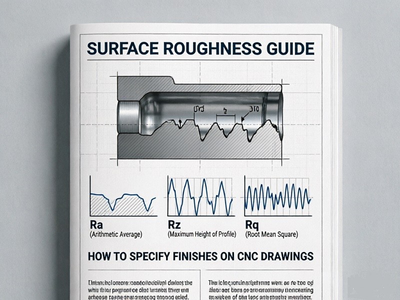
A single line on a drawing — Ra 0.8, Rz 10 — can decide whether a part seals under pressure, how long a bearing journal lasts, and whether your quote includes a grinding operation you never budgeted for. Surface roughness is one of the most consequential specifications on a CNC print, and one of the most frequently misunderstood. This guide explains what Ra and Rz really measure, what each machining process can realistically hold, how to write an unambiguous finish callout, and where chasing a smoother number stops paying for itself. Dimensional tolerances usually get the spotlight in design reviews. But the microscopic texture left on a machined surface drives friction, wear, sealing, coating adhesion, and fatigue life — often more directly than a diameter tolerance does. Global spending on surface roughness measurement reflects that growing importance: industry market analyses value the surface roughness measurement market at about USD 1.26–1.33 billion in 2026, with forecasts reaching roughly USD 2.27 billion by 2035 (a CAGR near 6.1–6.3%). The same reports point to rising demand from semiconductor fabrication, electric-vehicle manufacturing, and medical devices — sectors where micron-level surface texture can make or break performance. For buyers of custom CNC parts, the practical takeaway is simpler: how you specify surface finish on your drawings determines both how well the part functions and how much it costs. Specify a mirror finish where a standard machined finish will do, and you add 20–50% to the price of a component that never needed it. Specify too loose a finish on a sealing face, and you build in a leak or a premature wear failure. Surface roughness quantifies the fine peaks and valleys a cutting tool leaves behind. What looks smooth to the naked eye is, under a profilometer, a topography of tool marks shaped by feed rate, tool nose radius, spindle speed, and material behavior. Roughness is only one component of surface texture. Engineers distinguish three scales: Two parameters dominate real-world drawings: Ra and Rz. They are defined in ISO 4287 (and updated in ISO 21920-2:2021), with the US counterpart in ASME B46.1. Ra (Roughness Average) is the arithmetic mean of the absolute profile deviation from the center line over the sampling length. It is the industry default because it is stable, easy to measure, and simple to compare across suppliers. A typical general CNC callout is Ra 3.2 µm (about 125 µinch); precision functional surfaces commonly carry Ra 0.8 or 1.6 µm. Ra's blind spot: because it averages, a single deep scratch or high spike barely moves the number. A surface with one chatter gouge every few millimeters can still report an acceptable Ra while harboring a valley that acts as a seal leak path or a fatigue crack starter. Rz divides the profile into five sampling lengths and averages the vertical distance from the highest peak to the deepest valley within each. Because it captures extremes rather than averaging them away, Rz is the better predictor of performance for sealing surfaces, coating adhesion, and fatigue-loaded features. An often-quoted rule of thumb is Rz ≈ 4–7 × Ra, but the ratio depends on the process — turning, grinding, and EDM produce different Rz/Ra relationships at the same Ra value. Never "convert" Ra to Rz on a drawing and assume the result is enforceable. If extremes matter, specify the parameter that measures them. Fluid and gas paths typically need Ra 0.8 µm or smoother — and often an Rz limit — so O-rings and gaskets seat without micro-leak paths. Smoother sliding interfaces reduce friction and adhesive wear. Controlling Rz on hydraulic rods prevents a single spike from tearing a seal. Fatigue cracks initiate in the valleys of rough surfaces. Specifying sensible roughness on stressed fillets and shafts extends component life. Every step smoother than needed adds cycle time and often a secondary process. Function-first finish selection keeps quotes competitive. Knowing what each process realistically delivers — before you release the drawing — prevents the most common over-specification error in the industry: writing Ra 0.4 µm on a milled surface and discovering that the only way to hit it is grinding that was never in the process plan, budget, or lead time. Below roughly Ra 0.8 µm, standard CNC machining alone becomes unreliable for consistent batch-to-batch output. The step change at 0.8 µm marks the boundary where a secondary operation — grinding, honing, or polishing — is normally required. A useful model from machining practice: in turning, theoretical roughness follows Ra ≈ f² / 32R, where f is feed per revolution and R is the tool nose radius. Because the relationship is quadratic, halving the feed cuts Ra by about 75% in theory. In practice, feeds below roughly 0.05 mm/rev make the tool rub rather than cut cleanly — so there is a real floor to what feed reduction alone can buy you on a lathe. Choosing the right parameter is as important as choosing the right value. Two surfaces can have identical Ra yet behave completely differently under a seal or a fatigue load. Field example from our shop floor: a hydraulic manifold sealing face specified only as Ra 0.8 µm kept failing bench tests even though Ra was in tolerance. Adding an Rz limit exposed isolated deep scratches from a worn insert that Ra had averaged away. The fix — a tooling change and an Rz 3.2 µm cap — eliminated the intermittent leaks without any change to the Ra value. Specifying finish is a four-step discipline. Get these right and your supplier can quote, machine, and inspect without ambiguity. Legacy prints sometimes use N-grades (N1–N12), a simplified ISO scale where each grade maps to an Ra band — N8 corresponds to roughly Ra 3.2 µm, N7 to Ra 1.6 µm. If you inherit an N-grade drawing, convert it to an explicit Ra/Rz callout for clarity. Finish cost does not rise linearly with smoothness — it escalates in steps. A commonly cited model for relative machining cost: One documented production case is instructive: an aluminum housing mounting face was specified Ra 0.4 µm — a value carried over from an unrelated drawing. The face had no sealing or sliding function; it was bolted to a gasket. After a design-for-manufacturability review relaxed the callout to Ra 3.2 µm, grinding was eliminated, machining time fell about 40%, and cost dropped roughly 33% — with identical functional performance. The takeaway is not "always specify rougher." It is specify the least-smooth finish that meets the functional requirement, and reserve fine finishes for the faces that actually seal, slide, or carry fatigue loads. Specification only matters if it can be verified. Two measurement approaches dominate CNC quality control: Standards give you the enforcement language: ISO 4287 defines the parameters, ISO 21920-2:2021 modernizes surface texture specification, and ISO 1302 governs how the callout appears on drawings. A capable supplier should state its measurement method and provide roughness reports on request for functional surfaces. SOMI Custom Parts machines CNC turning, milling, and drilling components for customers who need controlled, repeatable surface finishes — from standard as-machined surfaces to ground and polished sealing faces. Our quality system follows ISO 9001 practices, and our engineers review every print for finish callouts that are either unachievable by the specified process or unnecessarily expensive. If you are unsure whether a face should carry Ra 1.6, Ra 0.8, or an Rz limit, send us the drawing: our DFM feedback tells you what each option costs and whether your function really needs it. We can also advise on the finish needed before anodizing, plating, or powder coating — coatings interact with surface texture, and specifying the right pre-coat roughness improves adhesion without paying for grinding you do not need. Start by reviewing our CNC machining capabilities, explore our surface finishing options, or read more buyer's guides in our blog. When you are ready, send us your part files through our inquiry page and we will return a quote with finish recommendations you can actually verify. Ra is the arithmetic average deviation of the profile from the mean line — a stable, easy-to-compare overall measure. Rz averages the peak-to-valley height across five sampling lengths, so it captures isolated deep scratches and high spikes that Ra averages away. For sealing and fatigue-critical surfaces, Rz is often the more meaningful parameter. Standard CNC turning and milling typically deliver Ra 1.6–3.2 µm. With optimized finishing passes on aluminum, Ra 0.8–1.6 µm is achievable. Below about Ra 0.8 µm you usually need grinding; below about Ra 0.4 µm, honing or polishing. On stainless steel, expect Ra values to run 20–30% higher than aluminum at equivalent parameters. No. Roughness interacts with function. Hydraulic rods need Ra 0.2–0.4 µm to protect seals while retaining an oil film, but a bolted mounting face does just fine at Ra 3.2 µm. Over-specifying finish adds 20–50% cost for no functional benefit; under-specifying on a sealing face risks premature failure. Only as a rough sanity check. The empirical range is roughly Rz ≈ 4–7 × Ra, but the ratio is process-dependent — turning, grinding, and EDM behave differently. If extremes matter to your application, specify Rz directly rather than estimating it from Ra. Use the ISO 1302 symbol: the tip of the check-mark touches the controlled surface, and the value sits above the horizontal extension (for example, "Ra 1.6"). Add a horizontal bar when material removal is required. State the parameter explicitly, use standard values, and confirm the value is realistic for the process you plan to use. Surface roughness is not a cosmetic afterthought — it is a functional and financial specification. Ra gives you a stable, comparable average; Rz captures the peaks and valleys that actually cause leaks, wear, and cracks. Standard machining delivers Ra 1.6–3.2 µm, fine finishing reaches 0.8–1.6 µm, and anything smoother generally means grinding, honing, or polishing — and a cost multiplier to match. The discipline that separates good drawings from expensive ones is simple: specify the least-smooth finish that satisfies the function, write it in unambiguous ISO terms, and check it against process reality before release. Do that, and your parts will perform, your inspections will pass, and your machining budget will stay where it belongs. Ready to put this into practice? Share your drawing with SOMI Custom Parts — our engineers will review your finish callouts and tell you exactly what each one costs.
1. Introduction: Why Surface Roughness Deserves Your Attention
2. What Is Surface Roughness? Ra, Rz, and the Language of Texture
Ra — the arithmetic average
Rz — the mean peak-to-valley height
3. Key Benefits of Specifying Surface Finish Correctly
Reliable sealing
Longer wear life
Higher fatigue strength
Cost control
4. Achievable Surface Roughness by Machining Process
Process Typical Ra (µm) Optimized Ra (µm) Notes CNC turning 1.6–3.2 0.8–1.6 Wiper inserts on aluminum 6061 reach 0.4–0.8 in production CNC milling 1.6–3.2 0.8–1.6 Interrupted cutting adds variability; stainless runs ~20–30% rougher than aluminum Grinding 0.4–0.8 0.2–0.4 The standard route below Ra 0.8 Honing 0.2–0.4 0.1–0.2 Cylindrical bores, cross-hatch lay for oil retention Polishing / lapping 0.05–0.2 <0.05 Manual, high cost, reserved for optical and sealing faces EDM (finishing) 0.8–1.6 0.4–0.8 Recast layer must be considered for fatigue parts Why the threshold sits at about Ra 0.8 µm
5. Ra vs. Rz: Which Parameter Should You Specify?
6. How to Specify Surface Finish on CNC Drawings
7. The Real Cost of Over-Specified Finishes
Ra callout Relative cost index Typical process route Ra 3.2 µm 1.0× (baseline) Standard milling / turning Ra 1.6 µm 1.2–1.5× Fine finishing pass Ra 0.8 µm 1.5–2.0× Optimized finishing or light grinding Ra 0.4 µm 2.0–3.0× Grinding required Ra 0.2 µm 3.0–5.0× Fine grinding, honing, or polishing 8. How Surface Finish Is Measured and Verified
9. How SOMI Custom Parts Can Help
10. Frequently Asked Questions
What is the difference between Ra and Rz?
What surface finish can standard CNC machining achieve?
Is a finer finish always better?
Can I convert Ra to Rz on my drawing?
How do I mark surface finish on my drawing?
11. Conclusion