Rapid Prototyping with CNC Machining: CAD to Part in Days
- Share
- publisher
- SOMI Custom Parts
- Issue Time
- Aug 11,2026
Summary
Rapid prototyping with CNC machining turns a CAD file into a functional, production-grade part in days. This 2026 guide covers the CAD-to-part workflow, CNC vs 3D printing trade-offs, tolerances, costs, and how SOMI Custom Parts accelerates your prototyping.
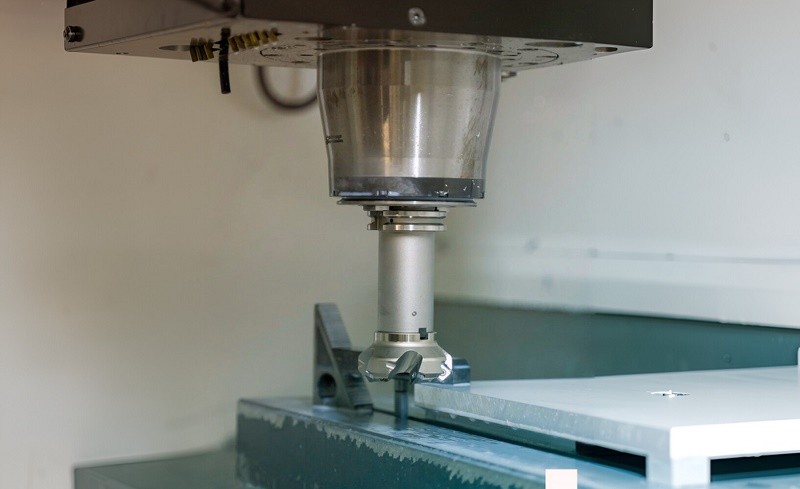
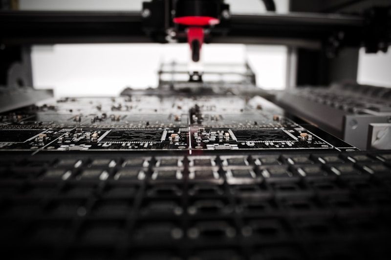
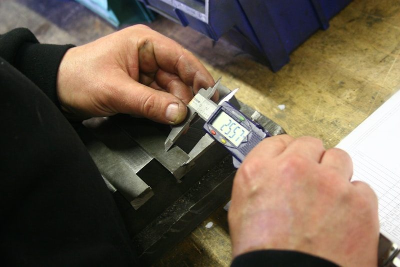
Every new product starts the same way: an idea trapped inside a CAD file, waiting to prove itself in the real world. Rapid prototyping with CNC machining collapses that wait from weeks to days, delivering functional, production-grade parts that you can test, load, and trust before you commit a single dollar to production tooling. Rapid prototyping with CNC machining is a subtractive manufacturing process that converts a digital CAD design directly into a physical part using computer-controlled cutting tools. The machine removes material from a solid block of metal or engineering plastic until only the finished component remains. Unlike additive 3D printing, which builds parts layer by layer from resin or powder, CNC machining starts with a certified billet of the exact material you plan to use in production. The prototype you receive is not a cosmetic model; it is a functional component machined to real tolerances, with the same mechanical properties as the final part. That is why engineers in aerospace, medical devices, automotive, and industrial equipment use CNC prototypes to validate fit, form, and function before scaling up. Prototype in the same alloys and plastics as final production, from 6061 and 7075 aluminum to stainless steel, titanium, PEEK, and POM. Solid billet stock preserves full material strength, unlike layer-bonded prints. Standard CNC tolerances hold ±0.05 mm, precision work reaches ±0.005 mm, and critical features can be held to GD&T specifications that 3D printing cannot match. As-machined surfaces typically measure Ra 0.8–3.2 μm, with Ra ≤ 0.4 μm achievable for sealing surfaces, bearing journals, and optical components. There are no molds to pay for and no tooling to wait on. Every design iteration is a software change, so you can test three revisions this week at a fraction of the cost of a tooling change. Because the same CAM program machines both prototype and production parts, approval of a prototype directly scales to low-volume runs of 50–500 units with no re-engineering. Machined prototypes come with material mill certificates, CMM inspection reports, and First Article Inspection (FAI) documentation that meet aerospace and medical compliance needs. Getting from a CAD model to a finished part in days is not magic; it is a disciplined seven-step workflow. Every step exists to remove uncertainty before the machine starts cutting. Submit your design as STEP, IGES, Parasolid, SolidWorks, or Fusion 360. Clean geometry with defined tolerances and surface finishes reduces back-and-forth before cutting begins. Engineers check wall thickness, tool access, internal corner radii, thread depths, and machining strategy. A good DFM review catches cost and time traps while the design is still free to change. CAM software converts the model into optimized toolpaths, selecting cutting tools, spindle speeds, feeds, and a roughing-to-finishing strategy for the specific material. Choose the material that matches final production requirements. Aluminum 6061 remains the most popular prototyping material because it machines fast, holds tolerances, and keeps per-part cost low. Three-, four-, or five-axis milling, turning, drilling, and boring transform the billet into your part. Five-axis centers machine complex geometry in a single setup, improving accuracy between features. Critical dimensions are measured on calibrated gauges and coordinate measuring machines (CMM). Dimensional reports and First Article Inspection reports document exactly what was delivered. Anodizing, bead blasting, passivation, plating, or PTFE coating complete the part before assembly and functional testing prove the design performs under real conditions. The question is never "which is better" but "which fits this design, this timeline, and this test plan." CNC machining wins whenever functional performance, material integrity, or certified traceability matter. 3D printing wins when geometry freedom, near-zero setup, or ultra-fast iteration matters. In practice, the smartest teams use both. Where costs cross over. Based on 2026 shop benchmarks, 3D printing is cheaper for one-off concept models, but CNC machining takes over as volume grows: a simple nylon bracket flips to CNC at roughly 50–60 units, and a titanium medical housing at roughly 70–100 units. A hybrid workflow, 3D printing design iterations and then machining the validated design, typically cuts total development timeline by about 40%. What you specify on the drawing determines what the prototype proves. Over-tolerancing every dimension inflates cost without adding value; under-specifying critical fits makes the test results meaningless. Apply tight tolerances only where they matter, typically mating surfaces and assembly interfaces. Right for most features, keeps machining time and cost down while delivering excellent functional performance. Reserved for critical features such as bearing seats, sealing surfaces, and press-fit diameters. Expect a 25–40% price uplift for GD&T tighter than ±0.005 mm. As-machined, bead blasted, anodized (Type II/III), passivated (ASTM A967), electroless nickel, PTFE, or powder coated. Prototype finish should mirror the final spec so assembly and wear behavior are validated early. The 2026 prototype shop looks different from the one ten years ago. Automated CAM logic generates toolpaths the moment a CAD file is uploaded, machines run lights-out overnight, and AI-driven adaptive control monitors spindle load and tool wear in real time. These advances have pushed tolerance capability to a ±0.005 mm baseline for critical components and made 24-hour functional prototyping a practical standard. Simple parts ship in 1–2 days. Typical one-off prototypes run 4–7 business days, with 2–3 day expedited service available at a 20–30% surcharge. Complex five-axis work in specialty alloys may take up to a week. CNC quotes split into a one-time setup fee ($80–$300 for programming, fixturing, and calibration) plus machining time. Setup is the biggest line item on a single-part order, so ordering 10–20 units amortizes it and cuts per-part price dramatically. Machine time is the biggest lever. A 5-axis hourly rate runs 30–50% higher than a 3-axis rate, yet 5-axis machines reach five sides in one setup, eliminating re-fixturing and often finishing cheaper overall. Keep designs 3-axis friendly where possible, and use five-axis only where compound angles or complex surfaces justify it. DFM is where experienced suppliers earn their keep. A review before quoting regularly identifies changes that cut machining time without affecting function. Largest internal radii. Use the biggest possible internal corner radius so standard end mills can finish the feature in one pass. Avoid walls under 0.8 mm. Thin walls invite vibration and warping, forcing slow, cautious cuts. Standard thread sizes. Off-the-shelf taps and inserts keep threading fast and inexpensive. Skip deep, narrow pockets. They need special tooling or EDM; simplify features that add no functional value. Tolerances on critical features only. Apply tight GD&T to mating surfaces, not the whole envelope. A prototype is only as valuable as its measurements. Reputable shops verify every critical dimension with calibrated instruments and document the results, so the data you test against is the data you can trust. Coordinate measuring machines verify critical dimensions across complex geometry, with reports documenting every measured value against the drawing. First Article Inspection reports and material mill certificates provide the auditable chain aerospace and medical programs require. Look for ISO 9001:2015 as the baseline, with AS9100 for aerospace and IATF 16949 for automotive programs. One hundred percent inspection before shipment is standard practice in modern prototype shops. SOMI Custom Parts is a precision contract manufacturer running 3-, 4-, and 5-axis CNC machining centers, CNC turning, and secondary finishing under one roof. We quote most prototype projects within 24 hours, review every drawing for manufacturability before cutting, and hold tolerances to ±0.005 mm where your design demands it. Because we machine prototypes from the same certified billet stock we use for production, your prototype test results translate directly to production parts. Our CNC machining parts service covers aluminum, stainless steel, titanium, PEEK, POM, brass, and copper, and our in-house finishing capability, anodizing, passivation, plating, and bead blasting, keeps quality control inside one quality system. We operate under an ISO 9001 quality system, provide CMM reports and FAI documentation, and work with no minimum order quantity so you can validate a single part before committing to a run. To see the range we machine every day, browse our product catalog, or read more about our approach in our company profile. Simple parts ship in 1–2 days. A typical one-off prototype takes 4–7 business days, and expedited service can deliver in 2–3 days. Complex five-axis parts in specialty alloys can take up to a week. Your lead time starts as soon as the design is DFM-approved. Choose CNC when you need real production materials, tight tolerances, certified traceability, or load-bearing mechanical performance. Choose 3D printing for complex internal geometries, lattices, or ultra-fast concept validation. Most product teams use both: print to explore geometry, machine to validate function. Standard machining holds ±0.05 mm across most features, and precision work reaches ±0.005 mm on critical dimensions. Tight GD&T below ±0.005 mm is possible but typically adds 25–40% to machining cost, so tolerance only what the design requires. Expect a one-time setup fee of roughly $80–$300 per design, plus machining time that scales with part complexity and material. Single units are the most expensive per part; ordering 10–20 units amortizes setup and sharply reduces unit cost. CNC becomes cheaper than 3D printing around 50–100 units for typical parts. Yes. Because the CAM program, fixtures, and inspection plan are identical, an approved prototype scales directly to low-volume production of 50–500 units with no re-engineering. This makes CNC prototyping the natural bridge between design validation and volume manufacturing. Rapid prototyping with CNC machining is the fastest reliable route from CAD to a part you can trust. It replaces weeks of waiting with days, cosmetic models with functional components, and guesswork with measured data. The discipline is simple: start with a clean CAD file, apply DFM early, machine from production-grade material, and verify with documented inspection. When your design is ready to prove itself, send your CAD file through our inquiry form for a quote, or contact our engineering team to discuss your prototype program. For more guidance on turning ideas into machined parts, explore the SOMI Custom Parts blog.From CAD to a Finished Part in Days: The Promise of CNC Rapid Prototyping
What Is Rapid Prototyping with CNC Machining?
Production-Grade Materials
Tight Tolerances
Real Surface Finishes
No Tooling Lock-In
Seamless Path to Production
Certified & Traceable
The CAD-to-Part Workflow: Seven Steps to a Functional Prototype
CAD Modeling and File Preparation
Design for Manufacturability Review
CAM Programming
Material Selection and Procurement
CNC Machining
Inspection and Verification
Finishing and Functional Validation
CNC Machining vs 3D Printing for Prototypes
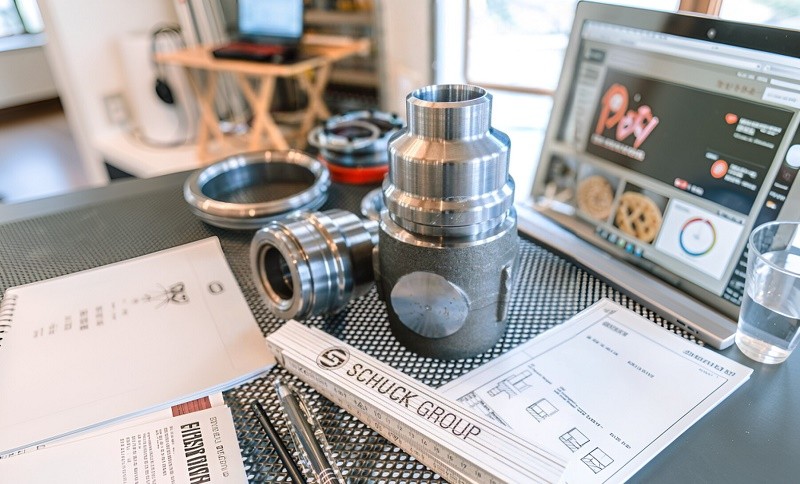
Factor CNC Machining 3D Printing Setup cost $80–$300 one-time per design $0 Single-part lead time 4–7 days standard, 2–3 rush 1–3 days Standard tolerance ±0.005–0.05 mm ±0.1–0.3 mm typical Surface finish Ra 0.8–3.2 μm as-machined Visible layer lines, post-processing required Material strength Full billet mechanical properties Layer-bond weakness, lower fatigue life Material choice Any machinable metal or plastic, certified stock Limited alloys and polymers 100-part batch lead time 7–12 days 10–18 days Best for Functional, load-bearing, certified parts Complex lattices, concept models, 1–20 units Tolerances, Materials, and Surface Finishes
Standard Tolerance ±0.05 mm
Precision Tolerance ±0.005 mm
Finishes That Match Production
Material Why Prototype With It Typical Applications Aluminum 6061 / 7075 Fast machining, low cost, good strength Housings, brackets, structural prototypes Stainless 303 / 304 / 316 Corrosion resistance, certified billet Medical, food, marine components Titanium Ti-6Al-4V Highest strength-to-weight, premium cost Aerospace, motorsport, implants PEEK High-temperature engineering polymer Aerospace and medical polymer parts POM (Delrin) Low friction, excellent dimensional stability Gears, bearings, precision plastic parts Brass / Copper Electrical and thermal conductivity Connectors, terminals, heat exchangers Lead Times and Costs: What to Expect in 2026
Realistic Lead Times
Realistic Costs
Design for Manufacturability: Speed Up Every Prototype Cycle
Quality Assurance: Inspection That Keeps Prototypes Honest
CMM Inspection
FAI and Traceability
Certified Quality Systems
How SOMI Custom Parts Can Help
Frequently Asked Questions
How long does CNC rapid prototyping take?
When should I choose CNC machining over 3D printing for a prototype?
What tolerances can CNC prototypes actually hold?
How much does a CNC prototype cost?
Can a CNC prototype be used for production?
Conclusion: From Concept to Confirmed Design