How CNC Turning, Milling, and Drilling Work for Precision Parts Manufacturing
- Share
- Issue Time
- Apr 13,2026
Summary
Explains CNC turning, milling and drilling working principles, processes, precision control and applications for custom high-precision parts manufacturing, solutions and cases.
As manufacturers, we are in a constant search for methods to create precise components efficiently and cost-effectively. For anyone involved in production, a deep understanding of key manufacturing processes like CNC turning, milling, and drilling is absolutely crucial for optimizing output and ensuring quality. This is where the power of Computer Numerical Control (CNC) machining comes into play, transforming digital designs into tangible, high-precision parts with unparalleled accuracy.
In this comprehensive guide, we will explore the fundamental principles, distinct applications, and core differences between CNC turning, milling, and drilling. Our goal is to demystify these advanced techniques, providing a clear and educational perspective on how they form the backbone of modern precision parts manufacturing. By understanding the unique strengths of each method, you'll be equipped to make informed decisions for your projects, ensuring you select the most effective process for your specific needs, from material choice to final part geometry.
Unveiling the Essentials: What Are CNC Turning, Milling, and Drilling Parts?
In the world of subtractive manufacturing, where material is removed from a solid block to create a final shape, CNC turning, milling, and drilling are foundational processes. While they all rely on computer-controlled instructions to achieve incredible precision, they operate on fundamentally different principles. Understanding these differences is the first step toward mastering the art of precision parts manufacturing and selecting the right technique for the job.
My Understanding of CNC Turning Parts
CNC turning is a quintessential machining process renowned for its ability to produce cylindrical or conical parts with high speed and accuracy. It is a cornerstone of manufacturing for components that exhibit radial symmetry.
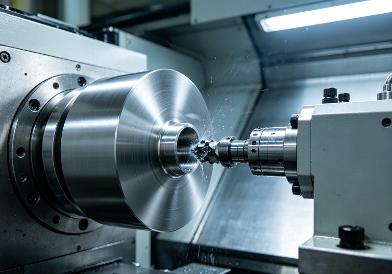
The Principle of Operation: Rotating Workpiece, Stationary Tool
The core principle of CNC turning is simple yet effective: the workpiece, which is a block of material (often a round bar), is held in a chuck and rotated at high speed. A stationary cutting tool, controlled by a computer, is then moved along the surface of the spinning workpiece to remove material and shape it. The tool itself does not rotate, but travels along two axes of motion: axially (along the length of the workpiece) and radially (across the diameter). This process is analogous to a traditional lathe, but with the precision and repeatability of computer control, allowing for the creation of intricate external and internal features on the part.
Ideal Geometries: Crafting Cylindrical CNC Turning Parts
CNC turning excels at creating parts that are symmetrical around a central axis. Because the workpiece itself is spinning, any feature that can be "drawn" by moving a tool along its length and diameter is a perfect candidate for this process. Common geometries and parts made through CNC turning include:
- Shafts: Straight, stepped, or tapered cylindrical rods used in countless mechanical systems.
- Bushings: Hollow cylinders that serve as bearings or spacers.
- Nozzles: Conical parts designed to control the flow of a fluid or gas.
- Fasteners: Custom bolts, screws, and pins with specific thread patterns and head shapes.
- Flanges: Protruding rims or collars used for an attachment point.
The process is ideal for creating smooth surfaces and features like grooves, tapers, and threads on round or hexagonal bar stock.
Exploring CNC Milling Parts: Complex Shapes and Intricate Details
Where turning is defined by a rotating workpiece, CNC milling is characterized by a rotating tool. This fundamental difference allows milling to create a much wider variety of complex, non-symmetrical shapes.
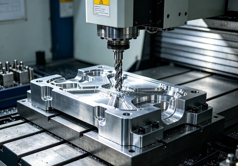
The Mechanics: Rotating Tool, Moving Workpiece
In CNC milling, the workpiece is held stationary on a movable table, while a multi-bladed cutting tool rotates at high speeds to cut away material. The computer controls the movement of both the table (and thus the workpiece) and sometimes the tool itself along multiple axes. The table can move left-to-right (X-axis), forward-and-backward (Y-axis), and up-and-down (Z-axis). This multi-axis movement enables the rotating tool to approach the workpiece from many different angles, carving out intricate features, pockets, and contours.
Perfect for Multi-Dimensional CNC Milling Parts
CNC milling is the go-to process for parts that are prismatic or have complex, non-cylindrical geometries. Its versatility makes it suitable for a vast range of components, often called "milled parts." Examples of geometries best suited for milling include:
- Engine Blocks: Complex metal castings with numerous flat surfaces, bores, and mounting points.
- Enclosures and Housings: Boxes or shells for electronic components that require precise cutouts, vents, and mounting bosses.
- Brackets and Mounts: Structural components with complex shapes, slots, and hole patterns.
- Molds and Dies: Tools used in injection molding or stamping, which often have intricate, three-dimensional surfaces.
Milling can create features like slots, pockets, flat surfaces, and complex 3D contours that are impossible to produce with turning alone.
The Role of Drilling in CNC Parts Manufacturing
While sometimes considered a standalone process, drilling in the context of CNC machining is most often an operation performed by either a CNC turning center or a CNC milling machine. Its purpose is singular and critical: to create holes.
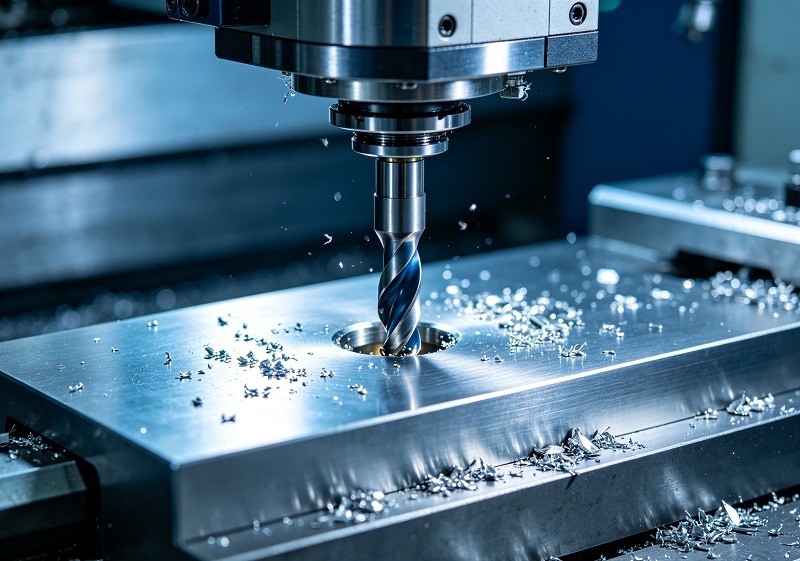
Creating Precise Holes with CNC Drilling
CNC drilling uses a rotating cutting tool, a drill bit, which is advanced into a stationary workpiece to create a round hole. The precision of CNC control ensures that holes are drilled to the correct diameter, depth, and location with incredible accuracy and repeatability, something that is difficult to achieve with manual drilling. These holes are essential for a wide range of functions, such as:
- Assembly: Creating passages for bolts, screws, rivets, or pins to join multiple parts together.
- Fluid or Air Flow: Channels within hydraulic manifolds or engine components.
- Weight Reduction: Removing material from a part without compromising its structural integrity.
CNC machines can also perform more advanced hole-making operations like tapping (to create internal threads) and reaming (to achieve a very precise diameter and smooth finish), making drilling an indispensable function in precision manufacturing.
Operational Deep Dive: The Distinct Processes of CNC Turning Milling and Drilling Parts
Moving beyond the basic principles, let's explore the step-by-step operational workflows that define the manufacturing of CNC parts. The journey from a digital model to a physical component involves distinct steps, from programming and setup to the intricate movements of the machine's axes. Understanding these workflows reveals how each process achieves its unique results and why a detailed approach is critical for the production of high-quality CNC Turning Milling and drilling Parts.
How We Make CNC Turning Parts: A Step-by-Step Guide
The turning process is a dance of rotation and precise linear movement. The quality of the final part is dictated by how well the machine controls the tool's path against the spinning material.
Focus on Axial and Radial Movements for Smooth Finishes
In a typical CNC lathe or turning center, the cutting tool operates on a two-axis system.
- Axial Movement (Z-axis): The tool travels parallel to the axis of the workpiece. This movement is used to control the length of features and to perform operations like turning down a long diameter or drilling a central hole.
- Radial Movement (X-axis): The tool moves perpendicular to the axis of the workpiece, moving in and out from the center line. This movement controls the diameter and is used for facing operations or creating contours, steps, and tapers.
The interplay between these two movements, combined with the rotational speed of the workpiece (spindle speed) and the rate at which the tool moves (feed rate), determines the final surface finish. A slower feed rate and higher spindle speed generally result in a smoother finish, as the cutting tool makes more passes over a given surface area.
From Facing to Threading: Versatile CNC Turning Operations
A single CNC turning center can perform a multitude of operations to create a complex part in one setup. These operations include:
| Operation | Description | Purpose |
|---|---|---|
| Facing | The tool moves across the end of the workpiece (along the X-axis) to create a flat, smooth surface. | To create a precise part length and a clean starting surface. |
| Turning | The tool moves along the side of the workpiece (along the Z-axis) to reduce its diameter. | To create different diameters, steps, and tapers. |
| Grooving | A specific tool plunges into the workpiece to create a narrow channel or "groove." | To create O-ring seats, recesses for clips, or simply decorative features. |
| Parting | A blade-like tool plunges into the workpiece to cut the finished part off from the main bar stock. | To separate the component after all other operations are complete. |
| Drilling | A drill bit is advanced into the center of the rotating workpiece. | To create a central hole. |
| Threading | A pointed tool makes multiple passes along the surface to cut helical threads. | To create external or internal screw threads for fasteners and fittings. |
Precision Workflows for CNC Milling Parts
CNC milling workflows are often more complex than turning due to the increased freedom of movement. The ability to manipulate the part and tool across multiple axes unlocks the potential for unparalleled geometric complexity.
Utilizing Multiple Axes for Unparalleled Complexity
The capability of a CNC milling machine is often defined by its number of axes.
- 3-Axis Milling: The most common type. The table moves in X and Y, while the tool moves in Z. It's perfect for drilling holes, machining flat surfaces, and creating pockets on one side of a part at a time. If machining is needed on another side, the part must be manually re-fixtured.
- 4-Axis Milling: This adds a rotational axis (the A-axis) to the 3-axis setup. The workpiece can be rotated, allowing the machine to work on multiple sides without a manual setup change. This is ideal for engraving on a cylinder or machining features around the circumference of a part.
- 5-Axis Milling: This adds a fifth axis of movement (the B-axis), which allows the tool head to tilt. By simultaneously moving all five axes, the machine can create incredibly complex 3D shapes, undercuts, and angled features in a single setup. This process, known as continuous or simultaneous 5-axis machining, is essential for aerospace components, medical implants, and complex molds.
Differences Between Vertical and Horizontal CNC Milling
Milling machines are also categorized by the orientation of their spindle (the part that holds and spins the cutting tool).
- Vertical Machining Centers (VMCs): The spindle is oriented vertically. This is the most common configuration, especially for smaller shops. VMCs are excellent for single-setup jobs where most of the work is done on the top surface of the part, such as creating pockets and drilling holes in a plate. Visibility is great, and they are generally less expensive.
- Horizontal Machining Centers (HMCs): The spindle is oriented horizontally. The workpiece is often mounted on a tombstone-like fixture that can rotate. HMCs are productivity powerhouses, allowing access to multiple sides of one or more parts in a single setup. A key advantage is chip evacuation; gravity helps chips fall away from the cutting zone, which can improve tool life and surface finish, especially in heavy-duty cutting.
Beyond Basic Holes: Advanced CNC Drilling Techniques
Drilling on a CNC machine is far more sophisticated than just making a simple hole. The process is integral to complex assemblies where hole quality, position, and features are critical for function and fit.
Why CNC Drilling is Integral to Complex Assemblies
For parts to be assembled correctly, the holes must be perfect. CNC control ensures this precision through a variety of advanced techniques:
- Peck Drilling: For deep holes (where the depth is several times the diameter), the drill bit retracts periodically to clear chips from the hole and allow coolant to reach the cutting edge. This prevents the drill from breaking and ensures the hole is straight.
- Reaming: After a hole is drilled, a reamer—a highly precise cutting tool—is run through it to slightly enlarge it to a very tight tolerance and produce an exceptionally smooth internal surface finish. This is critical for press-fit applications, like pins or bearings.
- Tapping: This operation uses a tool called a tap to cut internal threads into a pre-drilled hole, allowing a bolt or screw to be fastened.
- Boring: This process uses a single-point cutting tool to enlarge an existing hole and make it perfectly concentric. It can correct the location of a slightly off-center drilled hole.
- Counterboring & Countersinking: These operations create a stepped or conical feature at the top of a hole, allowing the head of a fastener (like a socket head cap screw or a flat head screw) to sit flush with or below the surface of the part. This is vital for aesthetics and function in many assemblies.
Comparing Performance: When to Choose CNC Turning Milling and Drilling Parts
Selecting the right manufacturing process is a critical decision that impacts cost, lead time, and the quality of the final component. The choice between CNC turning and milling is not always clear-cut, as many parts require a combination of both. However, understanding their core strengths will guide you toward the most efficient primary process for your project.
Workpiece Suitability: Cylindrical vs. Complex
The most fundamental deciding factor is the part's overall geometry.
- Choose CNC Turning for: Parts that are predominantly cylindrical, conical, or spherical. If the part possesses rotational symmetry, a lathe is almost always the most efficient starting point. Even if a cylindrical part needs some non-symmetrical features like a milled flat or cross-drilled holes, these can often be added as secondary operations on a "mill-turn" machine.
- Choose CNC Milling for: Parts that are primarily prismatic (squarish or rectangular) or have complex, freeform surfaces. If the core of your part is a block, plate, or irregularly shaped forging/casting, milling is the correct choice. It is ideal for creating features like pockets, slots, brackets, and complex 3D contours that are not based on a central axis.
Achieving Desired Surface Finishes and Tolerances
Both processes are capable of producing parts with very tight tolerances and excellent surface finishes, but the approach and typical results can differ.
- Surface Finish: Turning can naturally produce a very fine surface finish, especially on long, continuous diameters. The resulting finish often has a characteristic helical or phonograph-like pattern, which can be minimized with fine-tuned cutting parameters. Milling surface finish is a composite of many individual tool paths, which can create a more complex texture. However, with techniques like high-speed machining and specialized tools (e.g., face mills), milling can also produce mirror-like finishes on flat surfaces.
- Tolerances: Both technologies can hold tolerances in the range of ±0.001 inches (0.025 mm) or even tighter. The achievable tolerance depends heavily on the machine's quality, the rigidity of the setup, tool condition, and the material being cut. For extremely precise round features, turning or cylindrical grinding (a related process) is often preferred. For precise positional features (like the location of holes relative to each other), milling excels.
Production Volume and Material Considerations for CNC Parts
Cost-effectiveness is deeply tied to setup time, cycle time, and material choice.
- Production Volume:
- Turning: Often has a faster cycle time for simple round parts because the material removal rates can be very high. Setup is relatively quick, making it cost-effective for both prototypes and high-volume production of suitable parts.
- Milling: Setup can be more time-consuming, especially for complex 5-axis parts that require intricate fixturing. While cycle times can be long for complex geometries, modern HMCs with pallet changers can run nearly continuously on high-volume jobs, making them very efficient.
- Material Considerations: Both processes can handle a vast array of materials, including:
- Metals: Aluminum, steel, stainless steel, brass, titanium, and exotic alloys.
- Plastics: ABS, polycarbonate, nylon, PEEK, and acrylic.
- Composites: Materials like G-10 or carbon fiber (require special tooling and handling).
The choice of material will directly impact the cutting speeds, feed rates, and type of cutting tool required. Harder materials like stainless steel or titanium require slower speeds and more robust tooling compared to softer materials like aluminum.
The Impact of Axis Configuration on CNC Turning Milling and Drilling Parts
The complexity of the machine itself plays a major role in capability and cost.
- 2-Axis Turning: The simplest form, ideal for basic shafts and flanges. Very fast and cost-effective.
- 3-Axis Milling: The workhorse of the industry. Excellent for 2.5D parts (prismatic shapes with pockets and holes at various depths). Most economical milling option.
- 4 & 5-Axis Machining: These machines drastically reduce the need for multiple setups. By rotating the part (4th axis) or tilting the tool (5th axis), they can machine complex faces and undercuts in a single clamping. This significantly improves accuracy (as re-fixturing errors are eliminated) and can reduce overall lead time, though the programming and hourly machine rate are higher. A part that requires machining on all six sides would need six separate setups on a 3-axis mill, but could potentially be done in just two setups on a 5-axis mill.
Making the Right Choice: Optimize Your CNC Turning Milling and Drilling Parts Manufacturing
With a solid understanding of the processes and their performance characteristics, you can now make strategic decisions to optimize your manufacturing projects. This involves a holistic assessment of your part's requirements, from its initial design to the volume of production required.
Key Decision Factors for Our Manufacturing Projects
To select the most appropriate CNC process, ask yourself the following questions. Your answers will create a clear decision-making framework.
- What is the primary geometry of the part?
- Is it rotationally symmetric (a cylinder, cone, or disc)? -> Start with CNC Turning.
- Is it prismatic (a block or plate) or a complex, irregular shape? -> Start with CNC Milling.
- What level of complexity is required?
- Does the cylindrical part require off-center holes, slots, or flats? -> Consider a Mill-Turn Center.
- Does the prismatic part have deep pockets, undercuts, or contoured surfaces? -> May require 5-Axis Milling.
- What are the tolerance and surface finish requirements?
- Are the critical features precise diameters and roundness? -> Turning is a natural fit.
- Are the critical features the locations of holes or the flatness of a surface? -> Milling is better suited.
- What is the production volume?
- Prototype (1-10 parts): The fastest setup process might be best (often 3-axis milling or basic turning).
- Low to Medium Volume (10-1000 parts): Efficiency is key. Optimizing for fewer setups (e.g., using a mill-turn center) becomes valuable.
- High Volume (1000+ parts): Cycle time is dominant. Dedicated setups on highly automated machines (like a lathe with a bar feeder or a horizontal mill with a pallet pool) are most cost-effective.
- What is the material?
- Does the material require special handling (e.g., very hard or abrasive)? This will influence tool selection and machine rigidity requirements for both turning and milling.
Pros and Cons: A Quick Summary for CNC Parts
This table provides a high-level comparison to aid in your decision-making process.
| Feature | CNC Turning | CNC Milling |
|---|---|---|
| Best for Geometry | Cylindrical, conical, and round parts with axial symmetry. | Prismatic, non-symmetrical, and complex freeform parts. |
| Primary Process | Rotating workpiece, stationary tool. | Stationary workpiece, rotating tool. |
| Setup Complexity | Generally lower and faster for simple parts. | Can be higher, especially for complex multi-sided parts. |
| Cost per Part | Very low for high-volume simple round parts. | Can be higher due to longer cycle times and complex programming. |
| Typical Features | Diameters, grooves, threads, tapers. | Pockets, slots, flat surfaces, holes, complex 3D contours. |
| Limitations | Inefficient for creating non-symmetrical features without live tooling. | Less efficient for producing basic cylindrical parts. |
Exploring Combination Machines: Versatility for Our Smaller Shops
The line between turning and milling is blurring thanks to the rise of hybrid CNC machines.
- Mill-Turn Centers (or Multitasking Machines): These are advanced machines that integrate both turning and milling capabilities into a single, powerful platform. They feature a primary turning spindle and a separate milling spindle that can perform drilling, tapping, and complex contouring.
- Lathes with Live Tooling: This is a more common and affordable option where a CNC lathe is equipped with rotating tool holders in its turret. This allows the machine to stop the main spindle's rotation and use powered tools to mill flats, drill cross holes, or cut slots on a part that has just been turned.
The primary benefit of these combination machines is the ability to produce complex parts in a "Done-in-One" setup. By eliminating the need to move a part from a lathe to a mill, they drastically reduce setup time, labor costs, and the potential for errors that can occur during re-fixturing. For smaller shops, a single mill-turn machine can provide the capabilities of two separate machines, saving valuable floor space and increasing overall versatility.
In conclusion, the decision between CNC turning, milling, and drilling for manufacturing parts is not a matter of one being universally better than the others. Instead, it hinges on a careful and strategic assessment of your project's specific requirements, from the intricacy of the part's geometry and its material composition to the required production volume and budget constraints.
By understanding the unique strengths of each process—the rapid, efficient creation of cylindrical parts with turning, and the unparalleled geometric freedom offered by milling—we can strategically select the most efficient and cost-effective method. It is this informed choice that allows us to achieve unparalleled precision and quality in our finished components. We believe that a deep knowledge of these foundational CNC manufacturing processes is the ultimate key to elevating production standards, innovating with confidence, and delivering superior precision parts to the market.