DFM for CNC Machining: 10 Design Rules to Reduce Costs and Improve Quality
- Share
- publisher
- SOMI Custom Parts
- Issue Time
- Aug 2,2026
Summary
Master 10 DFM design rules for CNC machining to cut production costs, avoid geometry flaws, simplify machining and boost finished part consistency & quality.
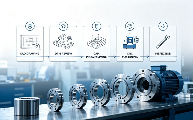
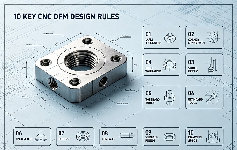
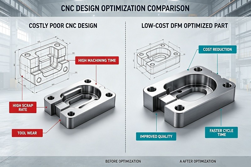
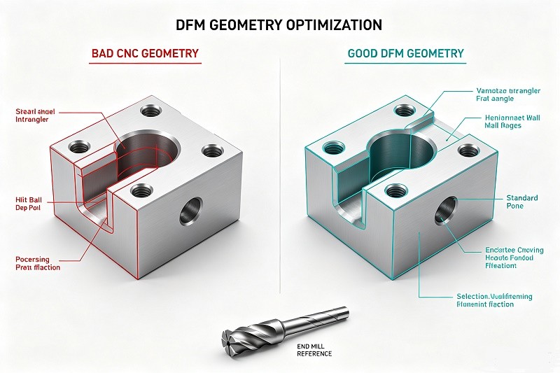
Buyer's Guide · Design for Manufacturability Design decisions lock in 70–80% of a part's manufacturing cost. These ten design-for-manufacturability rules show engineers how to cut CNC machining costs by 20–50% without changing how the part works. Design for Manufacturability (DFM) is the practice of shaping a part so it is easy and inexpensive to machine without changing its function. In CNC machining, the cost of a part is largely decided before the first chip is cut: research consistently shows that 70–80% of total production cost is locked in during the design phase. Once a drawing is released, most cost-reduction opportunities are gone. This guide distills the ten DFM rules that machining engineers at CNC machining shops most want designers to know. Applied together, these rules typically reduce piece-part cost by 20–50%, shorten lead times, and improve first-article pass rates from the industry average of 82–88% to 97% and above. The bottom line: the cost of changing a design before production is roughly 10× lower than fixing the same issue after tooling is committed. DFM is not an afterthought — it is concurrent engineering that starts at the concept stage. DFM for CNC machining means aligning every engineering decision — geometry, tolerances, materials, surface finish — with the real capabilities of milling, turning, and drilling operations. CNC cutting tools are round, rigid within limits, and expensive per minute of machine time. A design that ignores these realities quickly becomes slow to machine, expensive to inspect, or impossible to hold to tolerance. Typical DFM review checkpoints include tool access to every feature, wall thickness and deflection risk, tolerance stack-up against assembly requirements, surface-finish callouts limited to functional faces, and fixturing feasibility without part distortion. A good DFM review catches these issues while they are still free to change. Fewer operations, standard tooling, and relaxed non-critical tolerances reduce cycle time and inspection burden. Formal DFM reviews typically cut total production cost by 20–30%. Simplified geometry and fewer setups mean faster quoting, faster machining, and fewer mid-run surprises. DFM-optimized designs are quoted up to 40% faster. Parts designed within process capability pass first-article inspection (FAI) far more consistently, cutting scrap from 6–8% down to under 1.5% in production. Over-tolerancing is the single largest cost driver in CNC machining. Moving from a standard tolerance of ±0.13 mm (±0.005″) to a tight ±0.025 mm (±0.001″) can increase per-feature cost by 40–80% due to slower feed rates, additional inspection, and tighter process control. Rule of thumb: if more than 20% of your features carry a ±0.025 mm tolerance, you are over-tolerancing. Target 5–10% of features at tight tolerance and leave the rest at standard. Use GD&T per ASME Y14.5 to communicate functional intent, giving the shop flexibility in how it holds the specification. In one real project, a stainless steel connector specified a blind bore at ±0.005 mm; a DFM review showed the fit could be met at ±0.015 mm, cutting cycle time by 30% on a 50,000-piece run. Every unique hole diameter or non-standard feature requires a dedicated tool and a tool change — roughly 15 seconds each, plus tooling inventory and setup time. A part with 12 different hole sizes ties up 12 tools and 12 tool-change cycles. Best practice: consolidate drilled hole sizes to 2–3 standard diameters per part (fractional 1/8″, 3/16″, 1/4″ or metric 3 mm, 4 mm, 5 mm) and match holes to common fasteners. Standardizing to standard drills alone can save $5–10 per part in tool-change time. Similarly, design slots, radii, and threads around standard cutter sizes and standard thread forms (ISO metric coarse or UNC/UNF). Thin walls vibrate during cutting, producing chatter, poor surface finish, and dimensional errors. A 0.76 mm aluminum wall on a 75 mm span visibly deflects under cutting force, forcing operators to reduce feed rate by up to 80% — quadrupling cycle time. Minimums that work in practice: 0.8 mm for aluminum and 1.5 mm for steel; add ribs rather than removing wall material. Deep pockets need long, less-rigid tools. Keep pocket depth at or below 4× the pocket width; beyond a 4:1 ratio expect 20–40% higher cost and degraded finish. Internal corners are cut by round end mills, so sharp inside corners are physically impossible without EDM or hand finishing. Specify internal corner radii of at least one-third the pocket depth (e.g., 8 mm radius for a 25 mm deep pocket) — this alone can cut cycle time on affected pockets by 30–50%. Every setup costs 15–60 minutes of machine time plus re-alignment risk. A part machined in two setups is typically 30–40% cheaper than the same part in four setups. Design features so most are accessible from one or two directions, keep critical features on the same machining face, and add flat reference surfaces for clamping. For parts needing six-face access, compare a 5-axis single-setup quote against a 3-axis multi-setup quote. For tapped holes, limit thread engagement depth to 1–1.5× the fastener diameter in steel and 1.5–2× in aluminum; deeper threads add almost no pull-out strength but raise tap-breakage risk. Prefer through holes where possible and avoid pipe threads (NPT) on machined parts unless the application truly requires them — an O-ring seat (SAE J1926) usually seals better at lower cost. Material selection drives machining speed, tool wear, and cost. Aluminum 6061, brass, and mild steel machine fast and economically; stainless, titanium, and Inconel require slower speeds, premium tooling, and careful process control. Select the lowest-cost material that meets your mechanical, corrosion, and weight requirements. Surface finish should be specified only where it matters. The default as-machined finish of Ra 3.2 µm (125 µin) is fine for most non-functional faces. Specifying Ra 0.8 µm across an entire part forces extra finishing passes, cutting feed rates by 50–75% and adding cost. If anodizing, plating, or other coatings are required, plan for coating build-up in tolerance and flatness from the start. Tolerances: use standard ±0.13 mm unless function demands tighter; mark critical-to-function features. Holes: standard drill sizes only; consolidate to 2–3 diameters per part. Walls: keep ≥0.8 mm (aluminum) and ≥1.5 mm (steel); add ribs instead of thin walls. Pockets: depth ≤4× width; avoid deep narrow cavities. Corners: internal radii ≥1/3 of pocket depth; no sharp inside corners. Setups: design for 1–2 machining directions; align critical features on one face. Threads: engagement depth 1–1.5× diameter (steel), 1.5–2× (aluminum); through holes preferred. Materials: choose the most machinable grade that meets performance requirements. Finishes: Ra 3.2 µm default; specify tighter finish only on functional faces. Documentation: complete 2D drawings with tolerances, threads, finishes, and GD&T aligned to the 3D model. These rules are not theory. An analysis of 120 CNC production runs found an average 23.4% reduction in total production cost for parts submitted to a formal DFM review, saving roughly $19,890 per 1,000-piece order at an average part cost of $85. In a documented case, a robotics company's aluminum housing quoted at $147 per unit was redesigned through DFM — setups reduced from 6 to 3, two custom tool profiles replaced with standard end mills, and 14 non-functional tolerances relaxed — cutting cost by 27% in a single redesign. Industry benchmarks: DFM adoption runs at 85% among medical-device makers and 78% in aerospace, where average scrap drops from 4.8–5.2% to under 1.1% for DFM-reviewed designs. The global precision machining market reached roughly $132.9 billion in 2026 and is projected to grow at an 8.1% CAGR through 2033 — competitive advantage increasingly goes to design teams that engineer for manufacturability. At SOMI Custom Parts, DFM is part of every quote, not a paid extra. Our engineers review your CAD model and 2D drawings before production and flag cost drivers — over-toleranced features, deep pockets, non-standard tooling, thin walls — with concrete redesign suggestions, often before you even place the order. We machine aluminum, steel, stainless, brass, copper, and engineering plastics on 3-, 4-, and 5-axis CNC centers holding tolerances to ±0.005 mm, backed by ISO 9001 quality systems and in-house CMM inspection. From standard precision parts to fully custom components across automotive, medical, robotics, and industrial applications, our machining feedback helps you ship designs that are cheaper, faster, and more reliable. Send us your drawings for a free DFM review and quotation via our inquiry page, or contact our engineering team directly. Typical savings from applying DFM rules range from 20% to 50%. Tolerances, setups, and custom tooling are the biggest levers: relaxing non-critical tolerances and reducing setups alone commonly save 30–40%. Over-tolerancing. Specifying tight tolerances on non-functional surfaces adds 40–80% cost per feature without improving the part. The second most common mistake is designing sharp internal corners, which are impossible to mill with standard end mills. Yes. 5-axis machining removes many setup constraints and allows complex geometry in a single setup, but tolerance discipline, standard tooling, wall thickness, and finish rules still apply — and often matter even more because the parts are more complex. Absolutely. Reputable machining suppliers provide DFM feedback at the quoting stage. At SOMI Custom Parts we review every incoming design and recommend changes — usually at no charge — before committing to production. No. DFM removes cost without removing function: it keeps tight tolerances where they matter, adds rigidity through ribs, and simplifies features that deliver no value. DFM-reviewed designs typically achieve higher first-pass acceptance and lower scrap than un-reviewed designs. DFM for CNC machining is the cheapest insurance an engineering team can buy. Because 70–80% of part cost is decided at the design stage, the ten rules in this guide — disciplined tolerances, standard tooling, controlled wall and pocket geometry, fewer setups, and machinable materials — translate directly into lower quotes, shorter lead times, and fewer surprises on the shop floor. Whether you are prototyping a single part or ramping a production run, start with a DFM review. Explore our machining guides, browse our CNC machining capabilities, and send us your design for a free manufacturability assessment — the earlier we review it, the more you save.DFM for CNC Machining: 10 Design Rules to Reduce Costs and Improve Quality
Introduction: Why DFM Is the Highest-ROI Engineering Activity
What Is DFM for CNC Machining?
Key Benefits of DFM for CNC Machined Parts
Lower Cost Per Part
Shorter Lead Times
Higher First-Pass Quality
Design Rule 1: Avoid Unnecessary Tight Tolerances
Design Rule 2: Use Standard Tools and Standard Hole Sizes
Design Rule 3: Manage Wall Thickness, Pocket Depth, and Internal Corners
Design Rule 4: Reduce Setups and Standardize Threads
Design Rule 5: Choose Machinable Materials and Plan Finishes Early
Material Machinability Typical Use Cost Impact Aluminum 6061 Excellent Housings, brackets, EV parts Baseline — fastest, cheapest Brass / Copper Excellent Fittings, electrical parts Material premium, fast cutting Mild Steel Good Structural, industrial parts Moderate — balanced Stainless 304/316 Fair Medical, food, marine Slower feeds, more tool wear Titanium / Inconel Difficult Aerospace, high-temp Highest — premium tooling The 10 DFM Rules at a Glance
Real-World Results: What DFM Reviews Actually Deliver
How SOMI Custom Parts Can Help
Frequently Asked Questions
How much can DFM reduce CNC machining costs?
What is the most common DFM mistake in CNC part design?
Do DFM rules apply to 5-axis CNC machining?
Can a CNC shop help me redesign my part for manufacturability?
Does DFM reduce quality or force weaker designs?
Conclusion