CNC Machining for Optics and Photonics: Precision Housings, Mounts, and Fixtures
- Share
- publisher
- SOMI Custom Parts
- Issue Time
- Aug 27,2026
Summary
Learn how CNC machining creates the precision optical housings, mounts, and fixtures that keep photonics systems aligned to micron tolerances. From black anodized aluminum to Invar, discover the materials, tolerances, and surface finishes optical-grade machining demands, with SOMI Custom Parts as your ISO 9001-certified manufacturing partner.
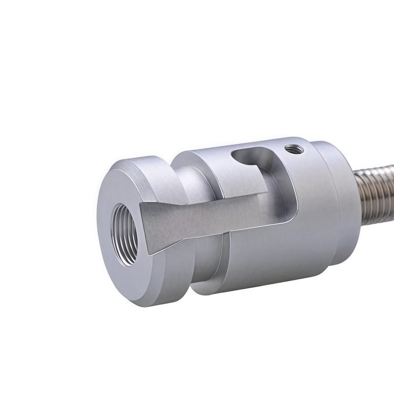
CNC Machining for Optics and Photonics: The Precision Backbone of Light-Based Technology
The global photonics market is projected to reach USD 1,046 billion in 2026 and grow at a 5.8% CAGR to USD 1,838 billion by 2036, driven by fiber-optic communications, industrial lasers, LiDAR, medical imaging, and quantum computing. What most buyers do not realize is that every one of those systems depends on precision-machined mechanical components—housings, mounts, and fixtures—that hold optical elements in micron-level alignment.
At SOMI Custom Parts, we machine the metal and polymer structures behind the lenses: optical housings, lens barrels, mirror mounts, kinematic bases, spacer rings, and alignment fixtures. This guide explains what makes opto-mechanical machining different, the tolerances that matter, the materials that stay dimensionally stable, and how to specify parts that keep your light path aligned.
What Is CNC Machining for Optics and Photonics?
CNC machining for optics and photonics refers to the precision manufacturing of the mechanical structures that house, align, protect, and thermally manage optical elements. These are not the lenses themselves—they are the lens barrels, optical mounts, sensor housings, fiber ferrules, kinematic bases, and test fixtures that keep lenses and mirrors exactly where the optical design requires them.
Photonics means the generation, detection, and manipulation of light. A laser diode needs a heat-dissipating housing; a fiber-optic transceiver needs a ferrule with bore concentricity in the single-digit-micron range; a LiDAR system needs a mount that survives temperature swings without beam drift. Every one of these components is a machined part, and the manufacturing discipline differs sharply from general industrial machining.
5-Axis Milling
Complex optical housings, mounts, and fixtures with controlled datums, bores, and pockets.
Precision Turning & Swiss
Spacer rings, retaining rings, ferrules, and cylindrical parts with tight concentricity.
Surface Finishing
Matte black anodizing, passivation, bead blasting, and plating for stray light and corrosion control.
CMM Inspection
Coordinate measuring machine verification of every critical feature, with traceable reports.
Key Benefits of CNC Machined Optical Components
Why do photonics manufacturers choose CNC machining over casting or 3D printing for structural parts? The answer lies in six capabilities that optical systems cannot compromise on:
Micron-Level Tolerances
Optical mounting surfaces routinely hold ±0.005mm or tighter, far beyond cast or printed accuracy.
Dimensional Stability
Stress-relieved machining and stable alloys keep alignment through thermal cycling.
Stray Light Control
Matte black anodizing and micro-textured surfaces suppress internal reflections.
Material Flexibility
Aluminum, titanium, Invar, stainless steel, brass, copper, and engineering plastics in one shop.
Batch Repeatability
CNC programs reproduce identical geometry from prototype to production volumes.
Fast Iteration
Engineering samples and small batches ship in days, accelerating R&D cycles.
Precision Tolerances and Geometric Control for Optical Alignment
In optical systems, tolerance is not a number on a drawing—it is beam position, image sharpness, and coupling efficiency. A lateral fiber offset of just 1µm adds roughly 1 dB of insertion loss, and a perpendicularity error of 0.5° produces 8.7mm of beam deviation over a 1-meter path. That is why photonics components are specified in microns, not hundredths of a millimeter.
| Application | Typical Tolerance | Key Geometric Controls |
|---|---|---|
| Fiber coupling (multimode) | ±5 µm | Bore concentricity 5–10 µm TIR |
| Fiber coupling (single-mode) | ±1 µm | Ferrule bore concentricity, surface finish Ra 0.4 |
| Aerospace LiDAR beam steering | ±2 µm | Thermally stable housing, flatness 2–5 µm |
| Medical imaging lens trains | ±3 µm | Lens seating flatness, parallelism ≤10 µm |
| Quantum photonics waveguides | Sub-100 nm | Ultra-precision fixturing, cleanroom handling |
Geometric tolerances matter more than linear dimensions in opto-mechanics. Concentricity between the lens seating bore and the external mounting diameter controls optical centering; flatness of seating surfaces prevents lens tilt; parallelism keeps multi-element beam paths true. These features are best defined with GD&T per ASME Y14.5 and verified on a CMM calibrated to ISO 10360, with measurement uncertainty at least 10:1 versus the part tolerance.
Thermal reality check: a 100mm aluminum part grows 2.36µm per 1°C. If your optical assembly sees 20°C swings, that is 47µm of movement—orders of magnitude beyond the alignment budget. Temperature-controlled machining, inspection, and material selection are not optional for optics work.
Materials for Optical and Photonic Components
Material selection for opto-mechanical parts balances coefficient of thermal expansion (CTE), stiffness, machinability, weight, and surface-finish response. The table below shows how the most common choices behave at 100mm length under a 1°C temperature change:
| Material | CTE (ppm/°C) | Growth of 100mm part @ 1°C | Typical Use |
|---|---|---|---|
| Aluminum 6061-T6 / 7075-T6 | 23.6 | 2.36 µm | General housings, mounts, baseplates |
| Titanium Ti-6Al-4V | 8.6 | 0.86 µm | Airborne LiDAR, space instruments, defense |
| Stainless steel 303/304/316 | 16.0 | 1.17 µm | Vacuum parts, medical, corrosive environments |
| Invar 36 | ~1.2 | 0.12 µm | Laser benches, ultra-stable reference structures |
| Brass 360 / OFHC copper | 19–20 | ~1.9 µm | Fiber connectors, thermal management |
| PEEK 450G | 45 | 4.5 µm | Insulating, non-magnetic, low-outgassing spacers |
How SOMI machines to thermal spec: for critical optical benches, we use a multi-stage sequence—rough machining, thermal stress relief, then finishing passes. This prevents the "creep" that occurs when residual internal stress releases after installation, which is the #1 cause of dimensional drift in optical housings.
Surface Finishes for Stray Light Suppression and Stability
Surface texture is where optical precision either holds or falls apart. Standard machined surfaces at Ra 3.2µm are too rough for precision optical mounting—roughness peaks create point contacts instead of continuous seating, introducing micro-tilts that amplify into beam misalignment. Photonics finishes typically target:
| Surface Requirement | Ra Target | Typical Finish Process |
|---|---|---|
| General optical mounts | Ra 0.8 µm (32 µin) | Fine machining + bead blasting |
| Precision seating interfaces | Ra 0.4 µm (16 µin) | Precision turning / milling + polishing |
| Mirror-finish contact surfaces | Ra 0.025 µm (1 µin) | Diamond turning / lapping |
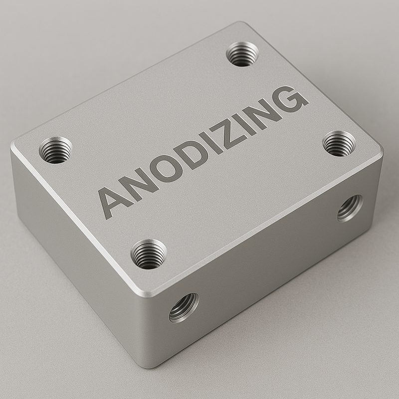
For stray light control, matte black anodizing is the workhorse: the micro-textured, non-reflective surface absorbs internal reflections and improves signal-to-noise ratio in imaging and sensing systems. Stainless steel parts receive passivation (ASTM A967) for corrosion resistance, while copper and brass components can be plated for conductivity and oxidation control. All finishing at SOMI Surface Finishing is done in-house, so dimensional verification happens before and after coating.
Optical Housings, Mounts, and Fixtures in Practice
Three component families cover most photonics machining work, and each demands its own machining strategy:
Optical Housings and Lens Barrels
Lens barrels and housings carry the optical elements and define the optical axis. They require precision bores concentric to external datums, controlled seating shoulders, and optical-quality threads (for example M25×0.5 to M52×0.75) with pitch accuracy of ±0.005mm. We machine these on 5-axis milling centers and precision lathes, holding bore-to-datum concentricity within 5–10µm TIR and seating-face perpendicularity within 0.002mm per 25mm of diameter.
Optical Mounts and Kinematic Bases
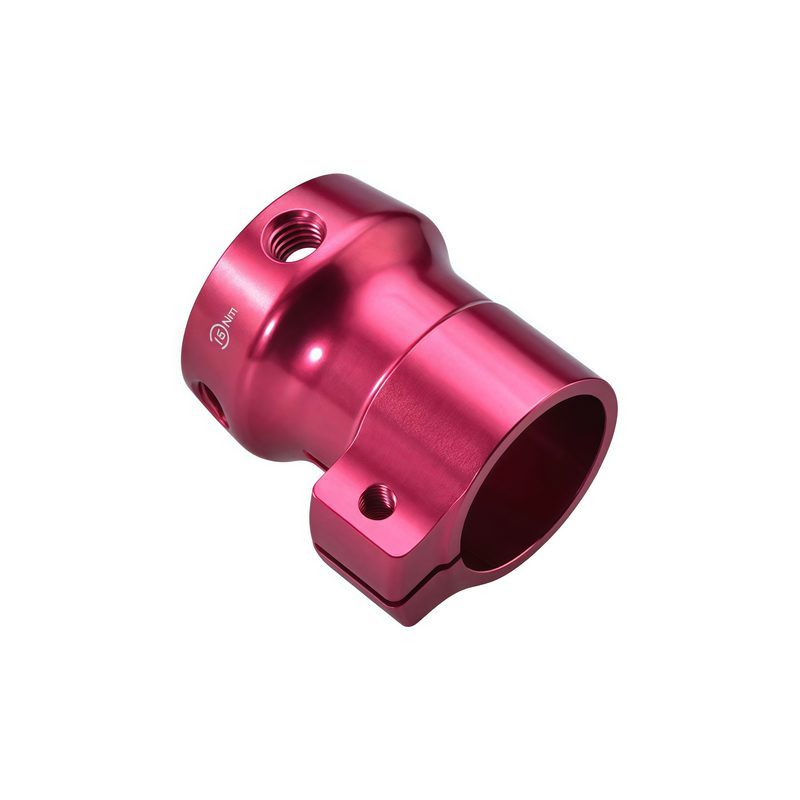
Mirror mounts, lens holders, and kinematic bases must provide angular stability over time. This means stable locating surfaces, threaded adjustment features, and stress-managed material. Invar 36 is specified when near-zero thermal expansion is required; titanium offers three times lower CTE than aluminum at higher cost. For precision work we combine multi-stage machining with CMM verification of all locating features.
Alignment Fixtures, Ferrules, and Connectors
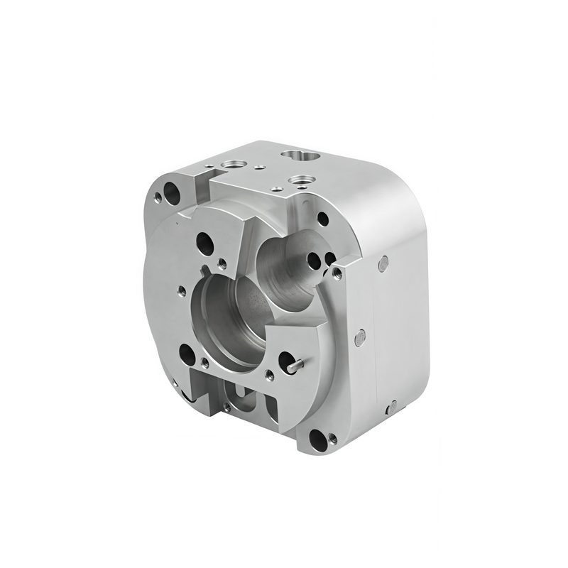
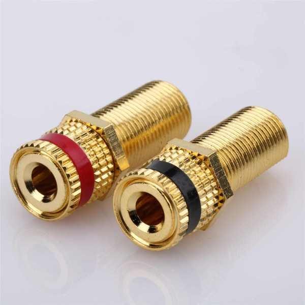
Fiber ferrules, V-groove arrays, connector housings, and alignment fixtures are where micron tolerances meet production reality. Bore concentricity on ferrule interfaces directly affects insertion loss, so these parts route through CMM inspection on every order. Swiss turning produces miniature cylindrical parts with ±0.005mm or better, while gold or nickel plating (as on our precision turned connectors) protects contact surfaces.
How SOMI Custom Parts Can Help
SOMI Custom Parts is an ISO 9001-certified precision manufacturer with dedicated CNC milling, CNC turning, and CNC drilling capabilities plus in-house surface finishing. For optics and photonics programs, we deliver:
- Optical-grade tolerances: machining to ±0.005mm with CMM verification and traceable inspection reports per ISO 10360.
- Finishing in-house: matte black anodizing, bead blasting, passivation, and plating under one roof—no hand-off delays.
- Material expertise: aluminum, titanium, stainless, Invar, brass, copper, PEEK, and more, with mill test reports on request.
- DFM support: our engineers flag thin-wall, undercut, and surface-finish risks before the machine runs, protecting your alignment budget.
- Prototype to production: engineering samples in days and repeatable batch production with no MOQ.
Browse our full product range to see the components we machine every day, or send your drawings for a DFM review and quote—we typically respond within 24 hours with a technical assessment of your tolerances, materials, and finishes.
Frequently Asked Questions
Does SOMI machine the actual lenses or optical glass?
No. We machine the mechanical components that hold and align optical elements—housings, mounts, barrels, ferrules, and fixtures—in metals and engineering plastics. Lenses and optical glass are produced by specialist optical fabricators.
What tolerances can you hold for optical mounting components?
We routinely machine to ±0.005mm, with bore concentricity of 5–10µm TIR and seating flatness of 2–5µm verified on a CMM. Critical features are documented with dimensional reports mapped to your drawing.
Which material is best for a thermally stable optical mount?
For most applications, 6061-T6 or 7075-T6 aluminum offers the best balance of stability, weight, and cost. If the assembly must hold alignment across wide temperature swings, titanium Ti-6Al-4V (CTE 8.6 ppm/°C) or Invar 36 (~1.2 ppm/°C) is specified.
Do you offer matte black anodizing for stray light suppression?
Yes. Our in-house surface finishing line provides matte black anodizing with a micro-textured, non-reflective surface, plus bead blasting, passivation, and plating—all verified after coating to ensure dimensional integrity.
Can you support prototype and small-batch optical projects?
Absolutely. We have no MOQ: a single optical prototype and a 5,000-piece production run follow the same workflow, with the same CMM inspection discipline and documentation.
Conclusion
Optics and photonics systems are only as precise as the structures that hold them. From lens barrels with 5–10µm bore concentricity to Invar laser benches that ignore temperature, CNC machining delivers the dimensional stability, surface quality, and repeatability that light-based technology demands. As the photonics market grows toward USD 1.8 trillion by 2036, the demand for optical-grade machined components will only accelerate.
When your next photonics project needs precision housings, mounts, or fixtures, partner with a manufacturer that treats microns as a specification, not a slogan. Contact SOMI Custom Parts today for a free DFM review and quote, or explore our technical blog for more precision manufacturing insights.