A Comprehensive Guide to Coaxial Connectors for UHF Male Connector Suppliers
- Share
- Issue Time
- May 25,2026
Summary
Complete guide to coaxial cables and UHF male connectors. Covers cable structure, key specs, RG types, shielding and common RF connector types for RF communication systems.
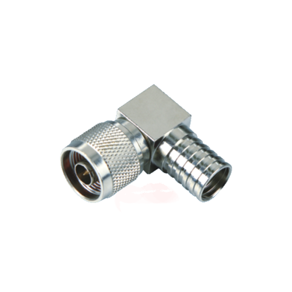
As a UHF male connector supplier, we understand the critical role that robust and reliable connectivity plays in today's high-speed communication landscape, impacting everything from military applications to everyday Wi-Fi. This guide is designed to empower you with a comprehensive understanding of coaxial cables and connectors, essential for ensuring signal integrity and system performance across diverse applications. We'll explore technical specifications, key connector types, and best practices to help you navigate the complexities of sourcing and supplying top-tier solutions to your clients.
The Foundation: RF Cable Types and Characteristics for Every UHF Male Connector Supplier
What Makes RF Cables Unique in High-Speed Data Transmission
In the realm of high-speed data and high-frequency signal transmission, not all cables are created equal. While standard electrical wires are sufficient for power and low-frequency signals, radio frequency (RF) cables are a specialized category engineered to handle signals from the megahertz (MHz) to gigahertz (GHz) range with minimal loss and distortion. The uniqueness of RF cables lies in their coaxial design, which is meticulously constructed to protect the signal from external electromagnetic interference (EMI) and prevent the signal from radiating outwards and causing its own interference. This structural integrity is paramount in applications where signal clarity is non-negotiable, such as in telecommunications, broadcasting, aerospace, and data centers.
Unlike simple shielded cables, which may only offer basic protection, RF coaxial cables function as transmission lines. This means their physical dimensions and material properties are precisely controlled to maintain a specific characteristic impedance, which is crucial for preventing signal reflections that can corrupt data. The concentric arrangement of conductors and insulation ensures that the electromagnetic field carrying the signal is contained entirely within the cable, enabling efficient, low-loss transmission over long distances. This containment and protection mechanism is what allows RF cables to support vast amounts of real-time data in modern avionics, facilitate clear connections to satellites, and deliver high-speed broadband internet to homes and businesses. Essentially, their specialized design makes them indispensable for any system where the integrity of a high-frequency signal is key to performance and reliability.
Deconstructing Coaxial Cable Anatomy and Its Core Components
To truly understand how RF cables achieve their exceptional performance, it's essential to dissect their anatomy. The term "coaxial" itself refers to the geometric arrangement of its components, which all share a common axis. This layered construction is the key to its ability to transmit high-frequency signals effectively while shielding them from interference. A typical coaxial cable is comprised of four main layers, each with a distinct and vital function.
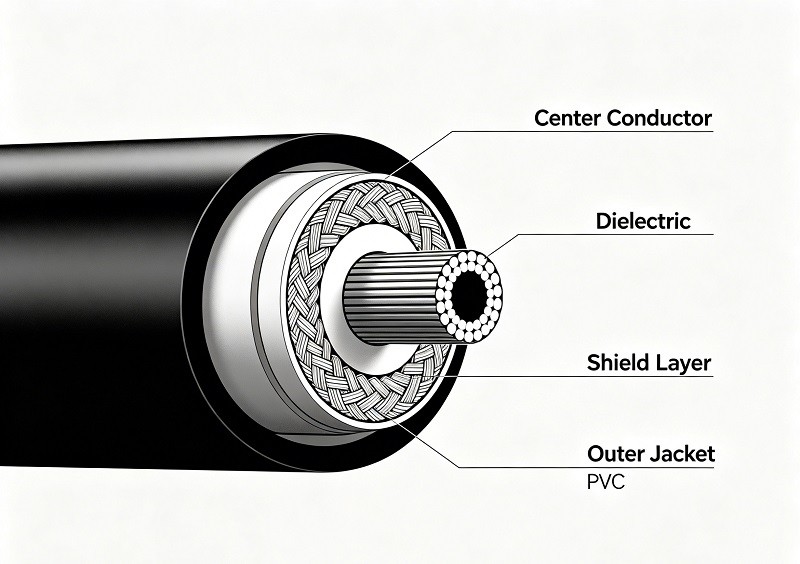
Here is a breakdown of the core components from the inside out:
Center Conductor: At the very heart of the cable is the center conductor. This is typically a single solid wire or multiple strands of copper, though sometimes copper-clad steel or aluminum is used. This component is responsible for carrying the actual RF signal in the form of an alternating electrical current. The choice between a solid or stranded conductor often involves a trade-off: solid conductors generally offer lower signal loss (attenuation), while stranded conductors provide greater flexibility for applications requiring movement or repeated bending.
Dielectric Insulator: Surrounding the center conductor is a layer of insulating material known as the dielectric. This layer is crucial as it maintains a precise, consistent spacing between the center conductor and the next layer, the shield. The dielectric material, commonly made of plastics like Polyethylene (PE) or Polytetrafluoroethylene (PTFE), is a poor electrical conductor and prevents the signal from shorting out to the shield. The material and thickness of the dielectric are primary factors in determining the cable's characteristic impedance and velocity of propagation.
Metallic Shield: The next layer is the metallic shield, which acts as the return path for the signal's current and, more importantly, protects the signal from external electromagnetic interference (EMI). This shield is usually a braided mesh of fine copper or aluminum wires, a solid foil layer, or a combination of both. The braiding provides a barrier against EMI from entering or exiting the cable, thus preserving signal purity. In environments with high levels of electronic noise, cables may feature multiple shielding layers (e.g., dual or quad-shield) for enhanced protection.
Outer Jacket: The final, outermost layer is the jacket. This is a non-conductive plastic coating, often made of PVC or a similar durable polymer, that encases all the internal components. Its primary purpose is to provide physical protection against moisture, chemicals, abrasion, and other environmental factors that could damage the cable's internal structure and compromise its performance.
Each of these components works in concert to create a controlled environment for the RF signal, ensuring it travels from source to destination with the highest possible fidelity.
Critical Performance Specifications: Impedance, Attenuation, and VSWR
When sourcing coaxial cables, suppliers must look beyond the physical construction and evaluate key electrical specifications that define a cable's performance. These metrics determine how a cable will behave within a system and are crucial for ensuring compatibility and signal integrity. The three most critical specifications are characteristic impedance, attenuation, and Voltage Standing Wave Ratio (VSWR).
1. Characteristic Impedance (Z₀)
Characteristic impedance is arguably the most fundamental specification of a coaxial cable. It is a measure of the opposition to the flow of AC current and is determined by the physical dimensions of the cable—specifically, the ratio of the outer conductor's inner diameter to the center conductor's outer diameter—and the dielectric constant of the insulating material between them. It is expressed in ohms (Ω). For maximum power transfer and minimal signal reflection, the impedance of the cable must match the impedance of the source, the load (e.g., an antenna), and the connectors. The most common impedance values are:
- 50 Ohm: Predominantly used in data transmission, wireless communication systems, and professional RF applications like test equipment and radio transmitters. 50 Ohm cables generally offer superior power handling capabilities.
- 75 Ohm: The standard for video and audio signals, widely used in cable television (CATV), satellite TV installations, and domestic hi-fi systems. 75 Ohm cables typically exhibit the lowest signal attenuation.
2. Attenuation (Insertion Loss)
Attenuation refers to the loss of signal strength, or power, as it travels through the length of the cable. It is a natural phenomenon caused by the resistive and dielectric losses within the cable. This specification is typically measured in decibels per unit length (e.g., dB per 100 feet or dB per meter) at specific frequencies. A critical rule to remember is that attenuation increases with both cable length and signal frequency. A lower attenuation value is always better, as it means more of the original signal power reaches the destination. For high-frequency or long-distance applications, selecting a low-loss cable is essential to maintain acceptable signal quality.
3. Voltage Standing Wave Ratio (VSWR)
VSWR is a measure of how efficiently RF power is transmitted from the source, through the cable, and into the load. It quantifies the amount of signal that is reflected back toward the source due to impedance mismatches. An impedance mismatch at any point in the system—between the cable and the connector, or the connector and the device—will cause some portion of the signal to be reflected. VSWR is expressed as a ratio, such as 1.5:1.
- A perfect match would have a VSWR of 1:1, meaning no power is reflected.
- A higher VSWR indicates a poorer match and more reflected power, which translates to a loss of signal strength delivered to the load.
For most applications, a VSWR below 1.5:1 is considered good, while values below 1.2:1 are excellent. As a supplier, understanding this metric is vital because a high VSWR can significantly degrade system performance, even if the cable itself has low attenuation.
| Specification | What it Measures | Common Values | Why It Matters for Suppliers |
|---|---|---|---|
| Impedance | The ratio of voltage to current in a traveling wave, determined by cable geometry. | 50 Ω, 75 Ω | Ensures compatibility and maximum power transfer between system components. |
| Attenuation | Signal power loss over the length of the cable. | e.g., 6 dB/100ft @ 1 GHz | Determines the maximum usable cable length for a given frequency and application. |
| VSWR | The ratio of reflected power to forward power due to impedance mismatches. | e.g., 1.2:1, 1.5:1 | Indicates the quality of the connection and overall system efficiency; a high VSWR is a red flag. |
By mastering these three specifications, a UHF Male Connector supplier can better guide clients in selecting the right cable assemblies to ensure optimal performance and reliability.
A Deep Dive into Coaxial Cable Design: Insights for UHF Male Connector Suppliers
While the basic four-layer anatomy of a coaxial cable is standard, the specific materials and construction methods used within those layers have a profound impact on performance. For a supplier, understanding these design nuances is key to stocking and recommending the right products for specific client needs, from high-power broadcasting to sensitive data communications.
The Role of the Center Conductor and Dielectric Material
The heart of the coaxial cable—the center conductor and its surrounding dielectric—dictates many of its primary electrical characteristics, including attenuation, power handling, and velocity of propagation.
Center Conductor: The center conductor's role is to carry the RF signal. Its material and structure are critical design choices.
- Material: Solid copper is a common choice, offering excellent conductivity and low resistance. For applications where cost or weight is a concern, Copper-Clad Steel (CCS) or Copper-Clad Aluminum (CCA) are used. The signal travels primarily on the copper surface at high frequencies (a phenomenon known as the "skin effect"), so these clad options provide a good balance of performance and economy.
- Structure: Conductors can be either solid or stranded. A solid conductor typically exhibits lower attenuation, making it ideal for fixed installations and applications where signal loss must be minimized. A stranded conductor, composed of many fine wires twisted together, offers significantly greater flexibility. This makes it the preferred choice for patch cables, test leads, or any application involving repeated movement and bending, though it comes at the cost of slightly higher attenuation.
Dielectric Material: The dielectric insulator is more than just a spacer; it is a critical component that governs the cable's electrical properties. Its primary roles are to maintain the precise distance between the conductors to ensure consistent impedance and to support the electromagnetic field that propagates the signal. The material's dielectric constant (εr) is a key parameter.
- Common Materials: Solid Polyethylene (PE) is a cost-effective and widely used dielectric. For higher performance applications, Polytetrafluoroethylene (PTFE) is the material of choice due to its very low dielectric constant and excellent temperature resistance.
- Foamed vs. Solid: To reduce the dielectric constant and lower signal loss, manufacturers often use foamed dielectrics. By injecting air or an inert gas into PE or PTFE, they create a material that is electrically closer to a vacuum (the "perfect" dielectric). This results in a higher velocity of propagation (the signal travels faster) and lower attenuation compared to a solid dielectric of the same material. Cables with foam polyethylene dielectrics can have a velocity factor ranging from around 0.80 to 0.88, compared to about 0.66 for solid polyethylene.
The interplay between the conductor's diameter and the dielectric's properties is what ultimately determines the cable's characteristic impedance, making the precise manufacturing of these two components essential for performance.
Understanding Shielding Types: Braided, Foil, and Dual Layers
The shield is a coaxial cable's primary defense against interference. Its job is to form a conductive barrier—a Faraday cage—around the inner conductor, intercepting stray electromagnetic fields and directing them to ground before they can corrupt the signal. The effectiveness of the shield, however, depends heavily on its construction.
Braided Shield: A braided shield consists of a mesh of woven metal wires, typically tinned copper or aluminum.
- Advantages: Braided shields are highly flexible and mechanically strong, making them durable and easy to terminate. They provide excellent protection against low-frequency interference (typically below 100 MHz).
- Disadvantages: Due to the nature of the weave, a braid cannot provide 100% coverage. Small gaps will always exist, which can allow high-frequency RF signals to leak in or out. A typical braid offers 70-95% coverage. While higher coverage is possible, it adds significant cost and weight.
Foil Shield: A foil shield is made of a thin layer of aluminum, often bonded to a polyester (Mylar) backing for strength and durability.
- Advantages: The primary benefit of a foil shield is that it provides 100% coverage, with no gaps. This makes it extremely effective at blocking high-frequency radio frequency interference (RFI) above 100 MHz. It is also lightweight and less expensive than a braided shield.
- Disadvantages: Foil is fragile and can be easily damaged by repeated flexing or sharp bends. Terminating a foil shield can also be more difficult, usually requiring a "drain wire" that runs alongside it to make a proper ground connection.
Combination (Dual-Layer) Shielding: For applications requiring the best possible protection across a wide range of frequencies, manufacturers combine both types of shielding. A common configuration is an inner foil layer with an outer braided layer (foil + braid). This hybrid design leverages the strengths of both:
- The foil layer provides 100% coverage to block high-frequency RFI.
- The braid layer adds protection against low-frequency EMI, provides a better path to ground, and adds significant mechanical strength and flexibility.
For even more demanding environments, "quad-shield" cables are available, which typically consist of two layers of foil and two layers of braid in an alternating pattern. This construction is common in high-quality CATV and satellite installations where signal integrity is paramount.
| Shield Type | Frequency Effectiveness | Coverage | Flexibility | Common Use Cases |
|---|---|---|---|---|
| Braid | Excellent (Low Freq < 100 MHz) | 70-95% | High | General RF, Industrial, Military |
| Foil | Excellent (High Freq > 100 MHz) | 100% | Poor | High-frequency data, CATV |
| Foil + Braid | Excellent (Broadband) | 100% + Braid | Moderate | Precision video, Industrial Automation |
Navigating RG-Type Cable Standards and Their Diverse Applications
The "RG" designation, which stands for "Radio Guide," is a legacy classification system originating from U.S. military specifications during World War II. While the formal military standard is now obsolete, the RG numbering system remains a universally recognized shorthand in the industry for identifying general categories of coaxial cable. However, it's crucial for suppliers to understand that an RG number no longer guarantees exact specifications; it serves as a general guide to a cable's characteristics and intended application.
Different RG cables are designed with varying impedances, conductor sizes, shielding types, and jacket materials to suit specific tasks. Matching the right RG cable to the application is fundamental to achieving reliable system performance.
Here are some of the most common RG-type cables and their primary applications:
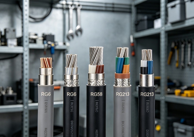
RG-6 (75 Ohm): This is the modern standard for home and commercial video and data distribution. It is universally used for cable television (CATV), satellite TV, and broadband internet connections. RG-6 features an 18 AWG center conductor, a thick dielectric, and robust shielding (often dual or quad-shield), making it well-suited for high-frequency signals over relatively long distances with low attenuation.
RG-59 (75 Ohm): An older standard, RG-59 is thinner and has a smaller center conductor than RG-6. Due to its higher signal loss at high frequencies, it has been largely replaced by RG-6 for broadband and digital TV. However, it remains a viable choice for low-frequency, short-run applications like older analog CCTV systems and some component video connections.
RG-58 (50 Ohm): This is a very common 50-ohm cable used for general-purpose RF applications. It's often found in Ethernet backbones (Thinnet, though now largely historical), ham radio setups, and as antenna feed cables for lower-power transmitters. Its flexibility makes it a good option for patch cables and test bench connections, but its relatively high loss makes it unsuitable for long runs at high frequencies.
RG-8 / RG-213 (50 Ohm): These are larger-diameter, lower-loss 50-ohm cables designed for high-power applications. RG-213 is a common choice for antenna feedlines in ham radio base stations, broadcasting, and other situations where power handling and low attenuation are more critical than flexibility. It is often considered a more rugged and higher-performance alternative to RG-8.
RG-174 / RG-316 (50 Ohm): These are thin, flexible coaxial cables designed for use in compact spaces. RG-174 is often used for short pigtail connections inside devices or for GPS antennas. RG-316 is similar but features a high-temperature FEP jacket, making it suitable for more demanding environments inside equipment or for aerospace applications. Both have significantly higher attenuation than larger cables and are only suitable for very short runs.
Understanding these common RG types and their respective applications allows a supplier to provide expert guidance, ensuring clients do not, for example, use a high-loss RG-58 cable for a long-run satellite installation that requires low-loss RG-6.
Decoding RF Connector Families: An Essential Guide for UHF Male Connector Suppliers
The connector is the critical link between the cable and the equipment, and its selection is just as important as the cable itself. A high-quality cable can be rendered ineffective by a poorly matched or low-quality connector. For suppliers, a deep knowledge of the different RF connector families, their coupling mechanisms, and their ideal applications is essential for providing complete connectivity solutions.
Threaded Connectors: Exploring SMA, N-Type, and the Ubiquitous UHF Connector
Threaded connectors are prized for their robust and secure mechanical connection, which provides excellent electrical performance and stability, especially in environments subject to vibration. The screw-on mechanism ensures a tight mate, which helps maintain consistent impedance and minimize signal loss.
SMA (SubMiniature version A): These are small, threaded connectors with a 50-ohm impedance, widely used in a variety of RF and microwave applications. Developed in the 1960s, SMA connectors are known for their high performance, offering reliable operation up to 18 GHz. Their compact size and excellent performance make them a staple in Wi-Fi equipment, mobile phone antennas, microwave systems, and handheld radios. They provide a very secure connection, making them ideal for both internal and external device connections where signal integrity is paramount.
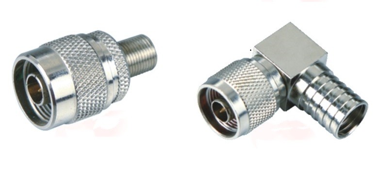
N-Type: Developed at Bell Labs in the 1940s, the N-type connector is a medium-sized, threaded, and often weatherproof connector capable of handling significant power. It was one of the first connectors designed to carry microwave-frequency signals and is available in 50-ohm and 75-ohm versions. Modern N-type connectors perform reliably up to 11 GHz and are renowned for their ruggedness and durability. They are a common choice for connecting to antennas, base stations, and high-power RF equipment, especially in outdoor or harsh environments where a secure, weather-resistant link is necessary.
UHF Connector (PL-259/SO-239): One of the oldest RF connectors still in widespread use, the UHF connector was designed in the 1930s for the radio industry. The name is a misnomer by modern standards; it was named when "Ultra High Frequency" referred to frequencies over 30 MHz. This connector series, consisting of the PL-259 (male plug) and SO-239 (female socket), is known for being rugged, affordable, and easy to assemble in the field. However, it has a significant drawback: it is a non-constant impedance connector. This impedance mismatch causes significant signal reflections and loss as frequency increases, limiting its effective use to frequencies below 300 MHz, with optimal performance being well below that. Despite this limitation, it remains the standard for HF and CB radio, amateur radio equipment, and marine VHF communications due to its durability and low cost.
Bayonet Style and Other Quick-Connect Solutions for Efficiency
While threaded connectors offer superior mechanical security, they are not always practical for applications that require frequent mating and de-mating. For these scenarios, bayonet-style and other quick-connect mechanisms provide an efficient and reliable alternative.
BNC (Bayonet Neill-Concelman): The BNC connector is perhaps the most famous bayonet-style connector. Mating is achieved with a simple quarter-turn of the coupling nut, which locks the connector securely in place. This design allows for very fast connection and disconnection without the need for tools. BNCs are available in both 50-ohm and 75-ohm versions and are widely used in a vast range of applications, including test and measurement equipment (like oscilloscopes), professional video systems (HD-SDI), and older computer networks. While standard BNCs are typically rated for use up to 4 GHz, specialized versions for broadcast can support frequencies as high as 12 GHz.
TNC (Threaded Neill-Concelman): The TNC connector is essentially a threaded version of the BNC. It was developed to address the BNC's tendency to radiate signals at higher frequencies and its susceptibility to unlocking under heavy vibration. The threaded coupling provides a more secure and stable connection, giving the TNC superior performance at microwave frequencies (up to 11 GHz) compared to the BNC. It is a popular choice in aviation, mobile communications, and other applications where vibration is a concern.
Push-On / Snap-On Connectors (SMB, SMC): For applications where speed is paramount, push-on connectors like the SMB (SubMiniature version B) offer a simple snap-on mating mechanism. SMB connectors are smaller than SMAs and provide quick, reliable connections in equipment where space may be limited. The SMC (SubMiniature version C) is a threaded variant of the SMB, offering a more secure connection in a similarly small form factor.
Specialized Connectors: High-Density and Micro Snap-On Options
The relentless trend of miniaturization in electronics has driven the development of incredibly small, high-performance RF connectors designed for use inside compact devices where every millimeter counts.
High-Density Connectors (MCX and MMCX):
- MCX (Micro Coaxial): Developed in the 1980s, MCX connectors are about 30% smaller than the already compact SMA connectors. They use a snap-on interface, which allows for quick assembly and is ideal for high-density applications on printed circuit boards (PCBs). They are commonly found in GPS devices, digital cellular equipment, and RF hardware.
- MMCX (Micro-Miniature Coaxial): As the name implies, MMCX connectors are even smaller than MCX connectors. They also feature a reliable snap-on mechanism and are designed for use in the most space-constrained applications. You will often find MMCX connectors in Wi-Fi cards, wearable technology, and other handheld devices where board space is at an absolute premium.
Micro Snap-On Connectors (U.FL, W.FL, MHF): These are among the smallest RF connectors available, designed for connecting antennas to PCBs inside extremely compact devices like laptops, smartphones, drones, and IoT modules.
- U.FL (and its compatibles like IPEX/MHF): These connectors have an extremely low profile, with a mated height of just a few millimeters. They provide a reliable snap-on connection for fine coaxial cables and are the de-facto standard for internal antenna connections in laptops and embedded systems. They are rated for use up to 6 GHz.
- Durability and Handling: While essential for modern electronics, these micro connectors are delicate and have a limited number of mating cycles (often around 30). They typically require a special tool for safe disconnection to avoid damaging the connector or the board.
Understanding this diverse landscape of connectors—from the rugged, high-power N-type to the minuscule U.FL—is crucial for suppliers to effectively serve the broad spectrum of RF applications their customers are working on.