A Comprehensive Guide to CATV Hardline Connectors: Types, Performance, and Selection Criteria
- Share
- Issue Time
- Jun 22,2026
Summary
Dive deep into the world of CATV hardline connectors. This guide compares pin-type and splice connectors, explains critical performance metrics like return loss, and offers expert advice on installation and selection to ensure long-term network reliability in a DOCSIS 4.0 world.
Why Every Millimeter Matters: The Critical Role of CATV Hardline Connectors
In the grand architecture of a Hybrid Fiber-Coaxial (HFC) network, it's easy to focus on the active components and the miles of cable. However, the integrity of the entire system often hinges on its smallest components: the connectors. A single, poorly installed or improperly chosen CATV hardline connector can introduce signal leakage, increase noise, and degrade performance across the entire network. As operators push network capabilities with standards like DOCSIS 4.0, which extends frequencies up to 1.8 GHz and beyond, the performance of these passive components is more critical than ever. Choosing the right connector is not just a technical detail; it's a strategic decision that impacts network reliability, maintenance costs, and future-readiness.
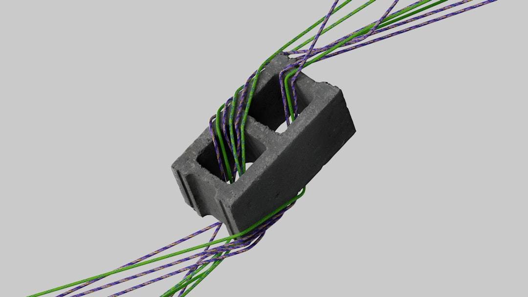
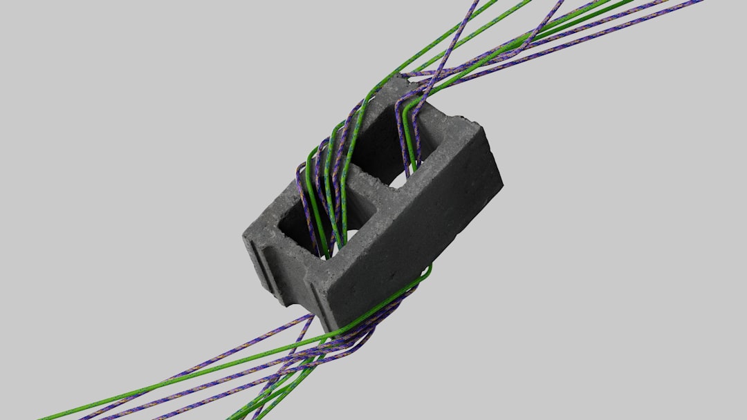
The Anatomy of a Hardline Connection
Before diving into the different types, it's essential to understand what a hardline connector does. Unlike the familiar connectors on a home TV, hardline connectors are engineered for the large, rigid coaxial cables used in the trunk and feeder portions of a CATV network. These connectors must achieve two primary goals: create a seamless electrical path for the RF signal and provide a robust, environmentally sealed connection. This involves making a secure connection to the cable's aluminum outer sheath and its solid copper or copper-clad aluminum center conductor.
H2: Core Connector Types: Pin vs. Splice
The two most fundamental categories of hardline connectors are pin-type and splice/feed-through connectors. While they both connect cable to equipment or other cables, they do so in fundamentally different ways.
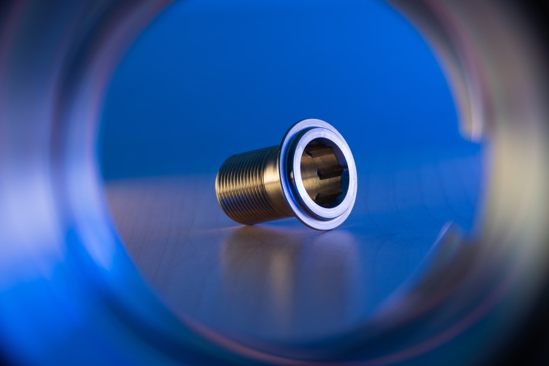
What are Pin-Type Connectors?
A pin-type connector, often-called a pin connector, is a three-piece assembly designed to terminate a hardline cable and connect it to an equipment port, such as on an amplifier or a tap. It features a long center "stinger" or pin that, once installed, acts as the new center conductor, which is then inserted into the equipment's seizure mechanism. The length of this pin is critical and must be trimmed precisely according to the equipment manufacturer’s specifications to ensure a proper connection.
What are Splice/Feed-Through Connectors?
A splice connector, also known as a feed-through or cable-to-cable splice, is used to join two separate pieces of hardline cable together. Unlike a pin connector, it does not have its own center conductor pin. Instead, it is designed to allow the cable's own center conductor to pass completely through the connector body, making direct contact with the center conductor of the cable on the other side. This creates a continuous, uninterrupted path for the signal.
H2: Key Performance Metrics You Can't Ignore
The quality of a connector is defined by its electrical performance. Two of the most important specifications are insertion loss and return loss.
- Insertion Loss: This measures the amount of signal strength lost as the signal passes through the connector. A lower number is always better, as it means more of the original signal gets through. High-quality connectors are designed to minimize this loss.
- Return Loss: This measures the amount of signal that is reflected back toward the source due to an impedance mismatch at the connection point. A high return loss value is desirable, as it indicates a clean, non-reflective connection. Poor return loss creates signal interference that can severely impact data-heavy services.
H2: Choosing the Right Materials: Brass vs. Aluminum
Connector bodies are typically made from either aluminum or brass, and the choice has significant implications for performance and durability. Aluminum connectors are lightweight but have a lower tensile strength (70-700 MPa). Brass, an alloy of copper and zinc, is significantly stronger and more durable (200-900 MPa). Brass is also less prone to galling (cold welding) on the threads, which means connectors can be disassembled cleanly without leaving behind metal shavings that could compromise the network. For long-term reliability, especially in harsh environments, brass is often the superior choice.
H2: The Importance of a Three-Piece Design
Many high-performance hardline connectors utilize a three-piece design (body, back nut, and internal components). This design allows for a more robust and reliable connection. As the back nut is tightened, it forces an internal seizing mechanism to clamp down securely on both the outer aluminum sheath and the center conductor. This independent seizing action ensures both mechanical stability and excellent electrical contact, which is vital for maintaining signal integrity under physical stress and temperature variations.
H2: Ensuring Longevity: Weatherproofing and Environmental Sealing
Hardline connectors are constantly exposed to the elements, from extreme heat and UV radiation to ice and salt spray. A failure in the environmental seal is a catastrophic failure for the connection. Moisture ingress is the number one enemy, leading to corrosion and immediate signal degradation. Modern connectors combat this with multiple O-rings and durable, corrosion-resistant platings. Additionally, for ultimate protection, every outdoor connection should be sealed with a two-step process: first, a layer of self-fusing silicone or rubber tape to create a moisture-proof barrier, followed by an overwrap of high-quality, UV-resistant electrical tape to protect the underlying layer from sun damage and abrasion.
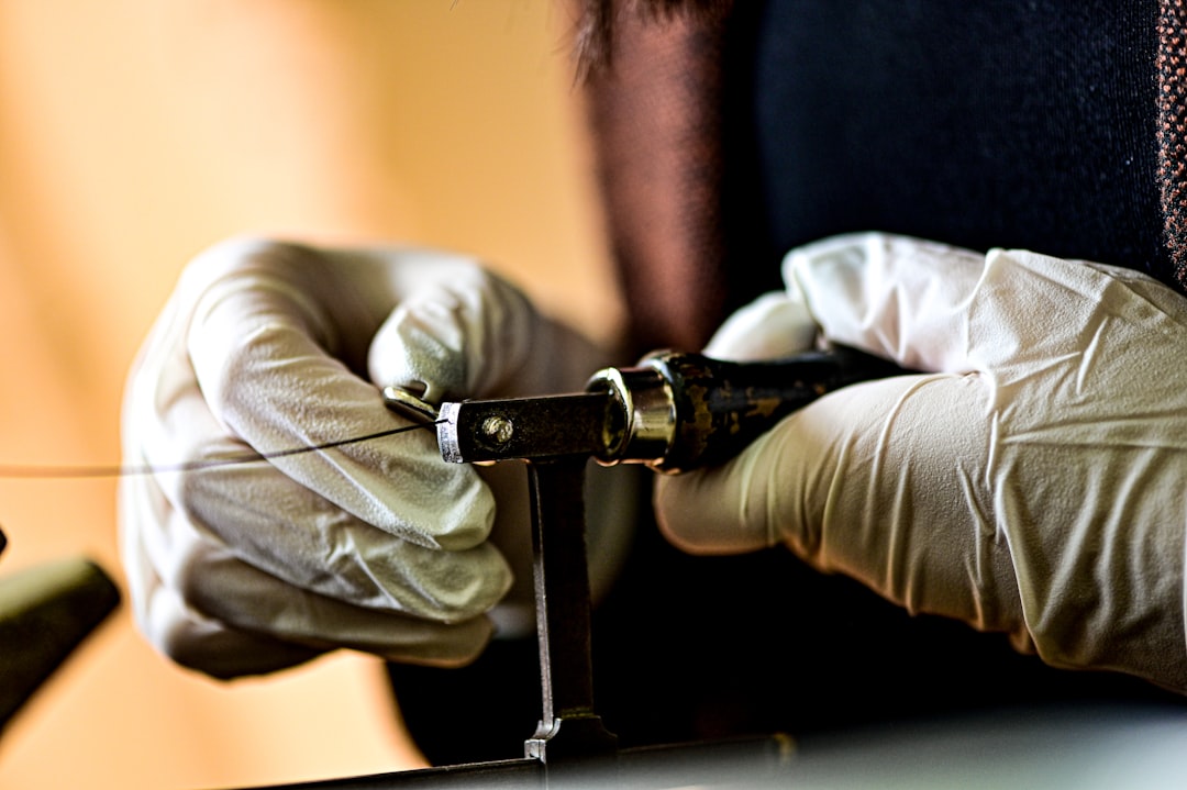
H2: Installation: The Craftsperson's Touch
A high-quality connector can be rendered useless by poor installation. Proper technique is not optional; it is mandatory for network reliability.
- Use the Right Tools: Always use dedicated hardline cable preparation tools, including a jacket stripper and a coring tool. Ensure blades are sharp and clean to avoid scoring the conductors.
- Clean Preparation: After coring the cable, ensure the center conductor is perfectly clean and free of any dielectric residue or cutting oils.
- Proper Tightening: Hand-tight is never enough. Use properly calibrated wrenches to tighten the connector to the manufacturer's specified torque. Some modern connectors feature a positive stop design that provides a clear physical and audible indication that the connection is complete.
- Correct Pin/Conductor Length: For pin connectors, use the guide on the equipment to trim the pin to the exact length. For splice connectors, ensure the center conductor is cut to the proper length as per the connector's instructions.
H2: Comparison Table: Pin-Type vs. Splice Connector
| Feature | Pin-Type Connector | Splice (Feed-Through) Connector |
|---|---|---|
| Primary Use | Connecting cable to equipment (taps, amps) | Joining two lengths of cable together |
| Center Conductor | Uses its own integrated pin ("stinger") | Uses the cable's own center conductor |
| Installation Step | Pin must be cut to a specific length | Cable's conductor must be cut to length |
| Signal Path | Signal transfers from cable to pin to port | Signal transfers from conductor to conductor |
| Example | 5/8" KS Pin Connector | .500" Cable-to-Cable Splice |
H2: Advanced Connector Features for a 1.8 GHz World
As network frequencies increase for DOCSIS 4.0, connector technology is advancing to keep pace. Some modern connectors employ advanced seizing mechanisms, such as a helix-shaped clamp that grips the center conductor over a larger surface area rather than at a single point. This provides a more stable electrical and mechanical connection, which is crucial for passing higher frequency signals seamlessly and reducing the risk of intermodulation distortion.
H2: Adapters and Specialty Connectors
The world of hardline connectivity extends beyond basic pin and splice types. A vast ecosystem of adapters and specialty connectors exists to solve various network challenges, including:
- Housing to Housing Adapters: Used to connect two pieces of equipment directly.
- Right-Angle (90°) Adapters: Essential for installations in tight spaces where cable bending is not feasible.
- Terminators: 75-ohm resistive loads used to cap off unused equipment ports to prevent signal reflections.
- F-Port Adapters: Allow for the connection of standard drop cables to a hardline tap or equipment port.
H2: The Final Connection: Making the Right Choice
Choosing the right CATV hardline connector requires a holistic approach. It’s not enough to simply match the cable size. You must consider the application (port or splice), the performance requirements (DOCSIS 3.1 or 4.0), the environmental conditions, and the need for long-term reliability. Investing in high-quality, well-designed connectors made from durable materials like brass and ensuring they are installed with precision and care, is a foundational step in building a robust, high-performance HFC network that can meet the demands of today and tomorrow.