10 Common CNC Design Mistakes and How to Avoid Them
- Share
- publisher
- SOMI Custom Parts
- Issue Time
- Sep 4,2026
Summary
Ten common CNC design mistakes raise machining cost, stretch lead times and scrap parts. This guide covers sharp internal corners, over-tight tolerances, deep pockets, thin walls and poor thread specification, and shows how a DFM review cuts cost by 15-40%.
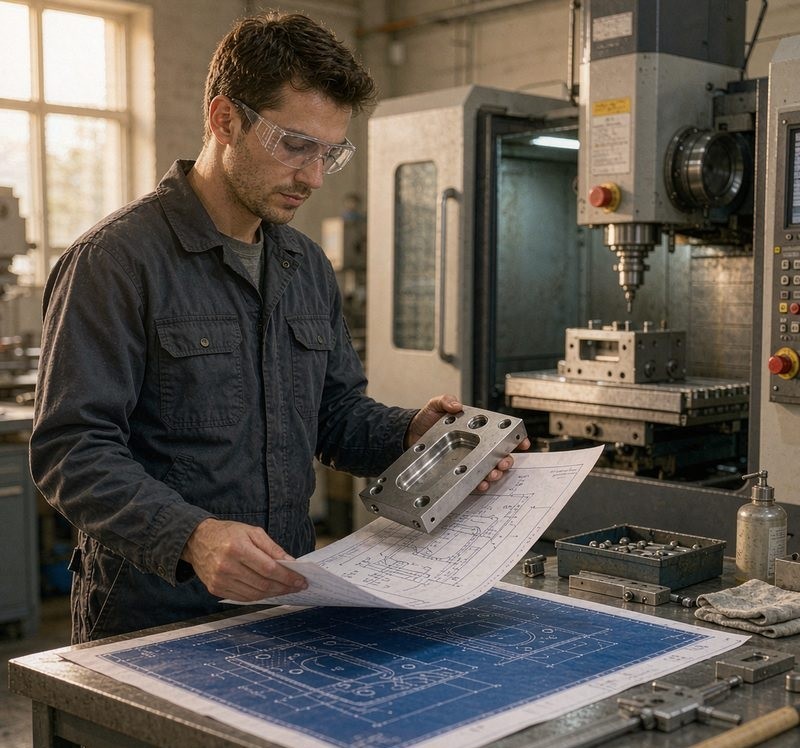
Every week, manufacturing engineers review drawings that look perfect on screen and turn out to be expensive on the shop floor. The reason is predictable: studies across the industry consistently show that 70–80% of a part’s manufacturing cost is locked in during the design phase, long before a single tool starts cutting. By the time a drawing is released, most cost-reduction opportunities are already gone. The good news is that the reverse is also true. Research from Modus Advanced and other DFM programs shows that a structured Design for Manufacturing (DFM) review reduces manufacturing cost by 15–40% and cuts lead time by up to 25%, with documented cases reaching 50%. Quality pioneer Philip Crosby’s famous 1-10-100 rule explains why: a design flaw that costs $1 to fix on a drawing costs roughly $10 to fix before production, $100 once parts are machined, and $1,000 after delivery. This buyer’s guide lists the ten most common CNC design mistakes our engineers see on incoming drawings, explains exactly why each one raises cost or risk, and gives you the concrete fix — the same notes our quoting team writes into a free DFM review on every project. The headline numbers in this guide: 70–80% of cost locked in at design · DFM review saves 15–40% · over-tolerancing adds 40–80% per feature · fixing a flaw after delivery costs up to 1,000× more than fixing it on the drawing. A CNC machining design mistake is any geometry, tolerance, material, or specification choice that conflicts with how real cutting tools, spindles, fixtures, and inspection equipment actually work. End mills are round, drills come in standard diameters, taps can snap, and long thin tools deflect. Designs that ignore these physical limits force slower feeds, special tooling, extra setups, more inspection, or outright scrap. Most problems fall into four families: Sharp internal corners, deep narrow pockets, thin walls, undercuts the tool cannot reach. Tight tolerances applied to every dimension instead of only functional interfaces. Non-standard holes, over-deep threads, finishes specified without coating thickness in mind. Hard-to-machine alloys chosen by strength alone, and reviews skipped before release. At SOMI Custom Parts, our engineering team runs a DFM review on every incoming file before quoting precision CNC machining parts. We flag these issues in the digital RFQ phase, where they cost nothing to fix, instead of on the shop floor, where they cost time and money. Below are the ten mistakes we catch most often, grouped by the stage of design they belong to. Use this table as a quick reference, then read the detailed sections that follow for the numbers and the fixes. This is the single most common mistake in CNC part design. A milling cutter is a rotating cylinder, so it physically cannot leave a perfectly square internal corner — the corner always follows the tool’s radius. A drawing that calls out a zero-radius corner either forces an expensive secondary process such as EDM, or a very small, fragile end mill running at dramatically slower speeds. The fix is simple and costs nothing in function: Getting this one right can cut cycle time on the affected pocket by 30–50%, because the machinist uses a large rigid tool instead of a small slow one. Lightweighting is a good instinct, but a wall that is too thin vibrates under cutting force. The tool chatters, the finish degrades, and the dimension wanders. In one documented example, a 0.76 mm aluminum wall over a 3” span deflected visibly during machining; the machinist had to slow the feed by 80%, which quadrupled cycle time, and the surface still came out scalloped. Deep cavities force the machinist to use a long, slender cutter that deflects under load. Deflection means wavy walls, poor finish, dimensional error, and — in the worst case — a snapped tool buried in your part. CNC tools need line of sight. A curved internal channel, a hidden T-slot, or a small feature deep inside a bore cannot be cut with a standard end mill. Undercuts are possible with special tools — lollipop and T-slot cutters — but only when they are accessible and have enough clearance, and they always cost more. Applying ±0.01 mm or ±0.001” to every dimension is the reflex that drives CNC quotes up fastest. Tight tolerances demand slower feeds, more frequent inspection, tighter environmental control, and more scrap. Cost does not rise linearly with precision — it climbs along a curve. Tolerance is not a quality score. It is a budget you spend only on the features that earn it. Every ±0.01 mm callout on a cosmetic face is money moved from your margin to the inspection bench. Every unique hole diameter on a part is a separate tool. A part with twelve different hole sizes needs twelve tools staged and twelve tool-change cycles of about 15 seconds each. Consolidating holes to 2–3 standard drill sizes (for example metric 3, 4, and 5 mm, or fractional 1/8”, 3/16”, 1/4”) saves an estimated $5–10 per part in tool-change time alone. Threads are a classic case of more not being better. Most of a screw’s pull-out strength comes from the first 1.5–2× the hole diameter of engagement. Specifying blind threads deeper than that adds machining time and, worse, invites a snapped tap — which can scrap the entire workpiece. Anodizing and plating add real thickness — typically 5–25 µm for decorative anodize, and more for hard coat or plating. If you machine a tight bore and then anodize it, the bore shrinks and your pin may no longer fit. Material choice is a manufacturing decision, not just a mechanical one. On the machinability index, aluminum 6061-T6 is the 100% reference; 316L stainless steel sits at 30–40%, and titanium and nickel alloys are lower still. A material that is hard to cut is slow to cut, wears tools faster, and can push machining cost to 3× or more versus a machinable alternative. The most expensive mistake is not in the geometry at all — it is releasing a design without a manufacturability review and approving production without a first-article inspection. Industry data ties roughly 25% of manufacturing quality issues at contract manufacturers to revision-control failures, and a wrong-revision production lot typically costs 5–20× the cost of the change process that would have prevented it. SOMI Custom Parts is an ISO 9001:2015-certified manufacturer of CNC machining parts, with in-house CNC milling, turning, drilling, surface finishing, and assembly under one roof. Because our engineers sit next to the machines, DFM is part of every quote, not an afterthought. Send your CAD and drawing; our team flags tolerance, geometry, thread, and finish issues before you commit to production — usually with lower-cost alternatives you can approve in minutes. Material test reports, first-article inspection, and CMM inspection reports accompany your parts, so the drawing you approved is the part you receive. Review a handful of parts first, then scale with confidence. The same DFM discipline applies whether you need one bracket or ten thousand. Ask us about corner radii, wall thickness, tolerances, or material choice before you finalize the file — we would rather help you upstream than rework parts downstream. Browse the full range of custom manufacturing services or read more CNC machining guides on our blog, and when you are ready, send your drawings through the inquiry page for a DFM review and a quote. Sharp internal corners with no radius. Because end mills are round, a square internal corner cannot be cut with standard tooling; it forces EDM or a very small slow cutter. Adding an internal radius of at least 1/3 of the pocket depth is the single highest-impact fix. Use standard machining tolerance, about ±0.1–0.13 mm (±0.005”), for most dimensions. Reserve tighter values — down to ±0.025 mm or ±0.01 mm — for the 5–10% of features that mate, seal, or bear load. Tightening everything adds 40–80% per feature for no functional gain. As a rule of thumb, about 0.8 mm for aluminum, roughly 1.0–1.2 mm for steel, and 1.5 mm or more for plastics. The safe value also depends on wall height and span — tall, unsupported thin walls vibrate and need ribs or a thicker section. Specify full thread engagement of about 1.5–2× the nominal diameter in aluminum and 1–1.5× in steel. Leave an unthreaded relief near the bottom of the hole and remember the drill-point cone adds extra depth. Deeper threads add cost and tap-breakage risk, not strength. Yes, and the earlier the better. At the RFQ stage, changes are free and instant: you approve a revised quote and drawing. Once material is cut, every change costs real money — up to 10–100× more. That is why SOMI runs a DFM review before we quote, so mistakes are caught while the only cost is a mouse click. Every one of the ten mistakes in this guide shares the same root cause: the design was optimized for the CAD screen instead of for the cutting tool. The fix is not more expensive machines — it is geometry, tolerances, and materials that respect how machining actually works, reviewed by people who run the machines every day. Apply the numbers from this guide — radii of at least 1/3 pocket depth, depth-to-width under 4:1, wall thickness above 0.8 mm, tight tolerance on 5–10% of features, threads engaged 1.5–2× diameter, materials matched to machinability — and your next quote will come back lower, faster, and with fewer surprises on the first article. When you are ready to turn a design into parts, send SOMI your drawings for a free DFM review and quote, or talk to an engineer before you finalize the file. If you found this guide useful, the rest of our CNC design and buying guides cover tolerances, materials, surface finish, and supplier selection in the same depth. Design smart, machine once.
Ten CNC Design Mistakes That Quietly Inflate Your Machining Quote
What Are CNC Machining Design Mistakes?
Geometry
Tolerancing
Features
Material & process
The Ten Mistakes at a Glance
# Mistake Typical penalty Best fix 1 Sharp internal corners with no radius EDM or slow tiny tools; +30–50% cycle time Internal radius ≥ 1/3 pocket depth 2 Over-tolerancing non-critical dimensions +40–80% per over-tight feature Tight tolerance on 5–10% of features only 3 Deep, narrow pockets +20–40% beyond a 4:1 depth-to-width ratio Keep depth ≤ 4× width, or split the part 4 Walls too thin to cut without vibration Feed cut by up to 80%; scrap and chatter ≥ 0.8 mm metal, ≥ 1.5 mm plastic 5 Too many or non-standard hole sizes +$5–10/part tool changes; custom tooling $80–350 Consolidate to 2–3 standard drill sizes 6 Blind threads specified too deep $1.20/part and 45 s extra per over-deep thread Engagement of 1.5–2× nominal diameter 7 Unreachable features and excess setups +30–40% for every extra setup Design for access from few directions 8 Material chosen without machinability Stainless can cost up to 3× aluminum to machine Match alloy to function, not just strength 9 Finish specified without coating allowance +50–75% finishing time on needless callouts Default Ra 3.2; state before/after plating 10 Skipping DFM review and first-article approval Errors multiply across the whole batch Free DFM check; approve FAI before production Geometry Mistakes: Sharp Corners and Thin Walls
Mistake 1: Designing sharp 90° internal corners
Mistake 4: Walls too thin to survive the cut
Cavity and Complexity Mistakes: Deep Pockets and Unreachable Features
Mistake 3: Deep, narrow pockets
Mistake 7: Features the tool cannot reach, and too many setups
Tolerance Mistakes: Precision Is a Commodity You Buy
Mistake 2: Over-tolerancing non-critical features
Holes, Threads, and Finishes: Feature-Level Mistakes
Mistake 5: Too many or non-standard hole sizes
Mistake 6: Threads specified without depth discipline
Mistake 9: Finishes specified without coating thickness or function
Material and Process Mistakes: Machinability, DFM Review, and FAI
Mistake 8: Choosing material on strength alone
Mistake 10: Skipping DFM review and first-article inspection
How SOMI Custom Parts Can Help You Avoid These Mistakes
Free DFM notes with every RFQ
Quality you can verify
From prototype to production
Engineers who answer
Frequently Asked Questions
What is the most common CNC design mistake?
How tight a tolerance should I actually specify?
What is the minimum wall thickness for machined metal parts?
How deep can a blind tapped hole be?
Can design mistakes be fixed after quoting?
Conclusion: Catch the Mistakes Before the Spindle Turns